February 2013
4-373
ColorQube® 9303 Family
REP 91.30
Repairs/Adjustments
REP 91.30 Drum Position Encoder Assembly
Parts List on PL 94.20
Removal
WARNING
Switch off the electricity to the machine. Refer to GP 14. Disconnect the power cord
from the customer supply while performing tasks that do not need electricity. Electricity
can cause death or injury. Moving parts can cause injury.
WARNING
Take care during this procedure. Sharp edges may be present that can cause injury.
1. Open front door.
2. Remove the inner cover, PL 81.11 Item 2.
3. Remove the front drum shroud, PL 94.20 Item 7.
CAUTION
Do not remove gold coloured screws from the encoder.
4. Remove the drum position encoder, Figure 1.
Figure 1 Encoder removal
Replacement
1. Replacement is the reverse of the removal procedure.
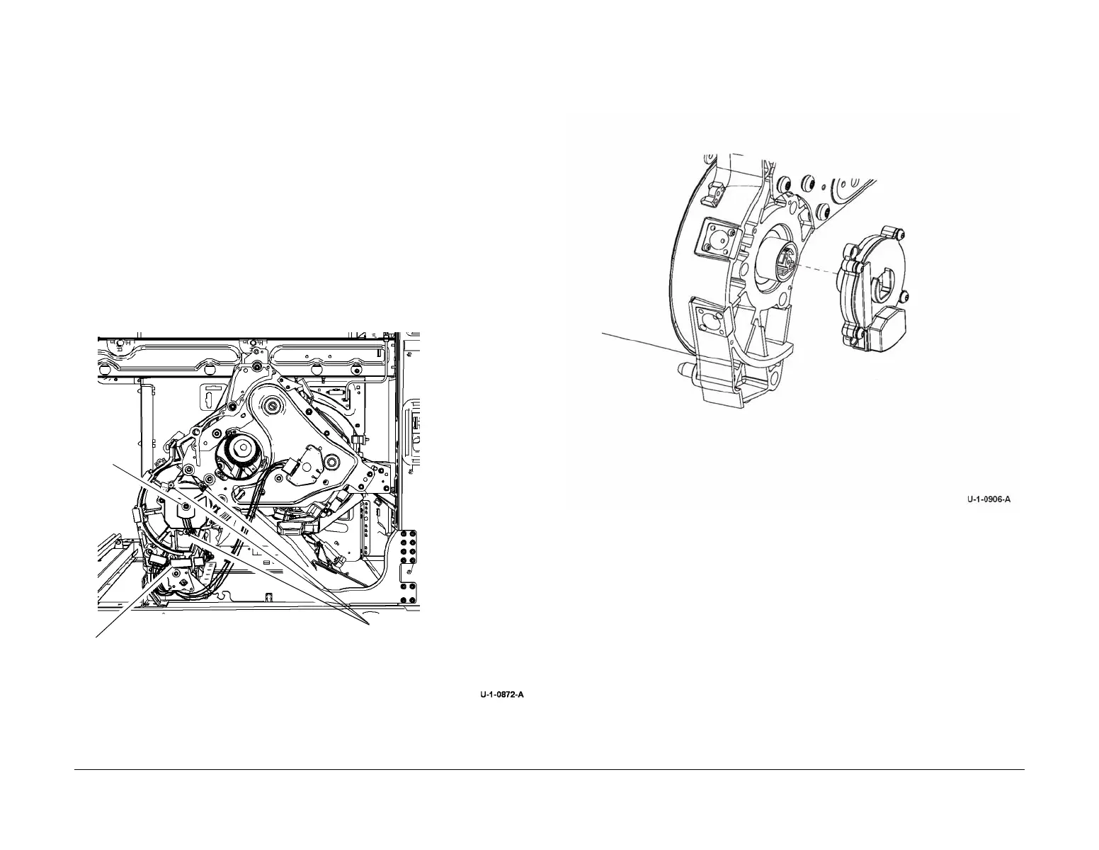
2. Orientate the encoder as shown in Figure 2. Feed the harness through the centre of the
encoder and align the drum heater bar with the centre opening.
Figure 2 Encoder replacement
3. Rotate the encoder until the screw holes line up and then press it on fully in this orienta-
tion.
4. Replace the lower and upper left screws. Replace the grounding plate, along with the cen-
tre and upper right screws.
5. Reconnect the harness.
6. Ensure the wiring is not pinched when replacing the ground plate and screw, Figure 1.
7. Run the relevant diagnostic routines, refer to GP 37 Post Part Replacement Routines.
1
Disconnect harnesses.
3
Remove 3 silver coloured
screws. See CAUTION.
Do not remove gold coloured
screws.
4
Pull encoder away
from the drum. Feed
the harness through
the centre of the
encoder.
A
2
Remove the ground plate
and centre screw, A.
 Loading...


