February 2013
viii
ColorQube® 9303 Family
Voltages Resistances and Tolerances
Introduction
Voltages Resistances and Tolerances
For AC power specifications, refer to GP 22 Electrical Power Requirements.
DC Voltage Levels and Tolerances
DC Voltages should be measured between an available test point and a machine ground.
Table 1 shows the range of the common voltages.
Non-standard voltage levels will be quoted on the relevant circuit diagram. All other voltage lev-
els are plus or minus 10%.
NOTE: During power self test and when in sleep mode, this supply is 17V unregulated and is
approximately +17V. When the machine is in active mode, this supply raises to +24V +/- 5%
Resistance Tolerances
All resistance measurement tolerances are plus or minus 10%, unless otherwise stated in the
procedure.
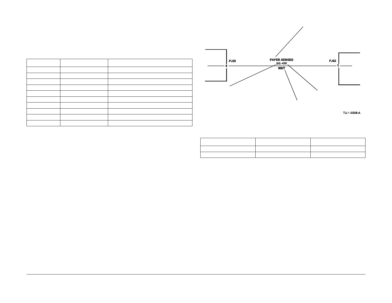
DC Signal Nomenclature
Figure 1 shows the signal nomenclature used in this manual.
Figure 1 Signal Nomenclature
Table 2 shows the signal tolerances.
Non standard signal tolerances will be quoted on the relevant wiring diagram.
NOTE: The logic level shown with the signal name will be the actual signal as measured with a
service meter. This will not necessarily be the same as the logic state shown on the diagnostic
screen.
Samples of RAP Reference Text
Throughout the manual there are linked references that extend the diagnostic procedure or
add more information:
• GP 11 How to Check a Sensor.
NOTE: This links to a General Procedure.
• WD 1.5
NOTE: This links to a relevant wiring diagram.
Install new components as necessary:
• Tray 1 feed sensor, PL 81.25 Item 19.
NOTE: This links to the parts list. If installation of the new component is simple, the parts
list artwork is sufficient to show how the component is assembled in the machine. If instal
-
lation of the new component is not simple, the parts listing will contain cross references to
repair procedures and adjustments, as necessary.
Table 1 DC Voltage Levels
Nominal voltage Voltage tolerance range RAP reference
0 volts 0.00 to 0.10V 01L 0V Distribution RAP
+3.3V ESTAR +/− 2.5% 01B +3.3V ESTAR Distribution RAP
+3.3V +/− 2.5% 01C +3.3V Distribution RAP
+5.V 5.1V +/- 5% 01D +5V Distribution RAP
+12V +/− 5% 01E +12V Distribution RAP
-12V +/− 5% 01F -12V Distribution RAP
+17V See Note 01G +17V Distribution RAP
+24V +/- 5% 01H +24V Distribution RAP
+50V 47V to 49V 01J +50V Distribution RAP
-50V -47V to -49V 01K -50V Distribution RAP
Table 2 Signal tolerances
Signal voltage (H) logic level (L) logic level
+5V +3.85V or greater At or near 0.8V
+3.3V +2V or greater At or near 0.8V
Signal description (event that
causes the signal level change)
Logic level when the
signal is available
Voltage supplied to
the signal circuit
Wire colour
 Loading...


