February 2013
4-50
ColorQube® 9303 Family
REP 5.12, REP 5.13
Repairs/Adjustments
REP 5.12 DADH Counterbalance
Parts List on PL 5.10
Removal
WARNING
Switch off the electricity to the machine. Refer to GP 14. Disconnect the power cord
from the customer supply while performing tasks that do not need electricity. Electricity
can cause death or injury. Moving parts can cause injury.
WARNING
Do not remove the DADH while the DADH is lowered. In the lowered position the coun-
terbalance springs are compressed and can cause injury when released.
WARNING
Take care during this procedure. Sharp edges may be present that can cause injury.
1. Remove the DADH, REP 5.19.
2. Put the DADH upside down on a solid flat surface.
NOTE: The counterbalances are different. The removal procedure for the two counterbalances
is same.
3. Remove the relevant counterbalance, right, PL 5.10 Item 2 (4 screws) or left, PL 5.10 Item
4 (4 screws).
Replacement
1. The replacement is the reverse of the removal procedure.
2. Perform the steps that follow:
• DADH height adjustment, ADJ 5.2.
• DADH registration adjustment, ADJ 5.5.
3. If a new right counterbalance has been installed, perform the DADH skew adjustment,
ADJ 5.3.
REP 5.13 Exit Roll Assembly
Parts List on PL 5.35
Removal
WARNING
Switch off the electricity to the machine. Refer to GP 14. Disconnect the power cord
from the customer supply while performing tasks that do not need electricity. Electricity
can cause death or injury. Moving parts can cause injury.
1. Remove the feed assembly, REP 5.3.
2. Remove the input tray assembly, REP 5.4.
CAUTION
Disconnect the ground harness from the static eliminator before the input tray assembly lower
cover left is removed, refer to Figure 1.
3. Turn the input tray assembly upside down. Remove the Lower cover (right), PL 5.35 Item
9 and Lower cover (left), PL 5.35 Item 20.
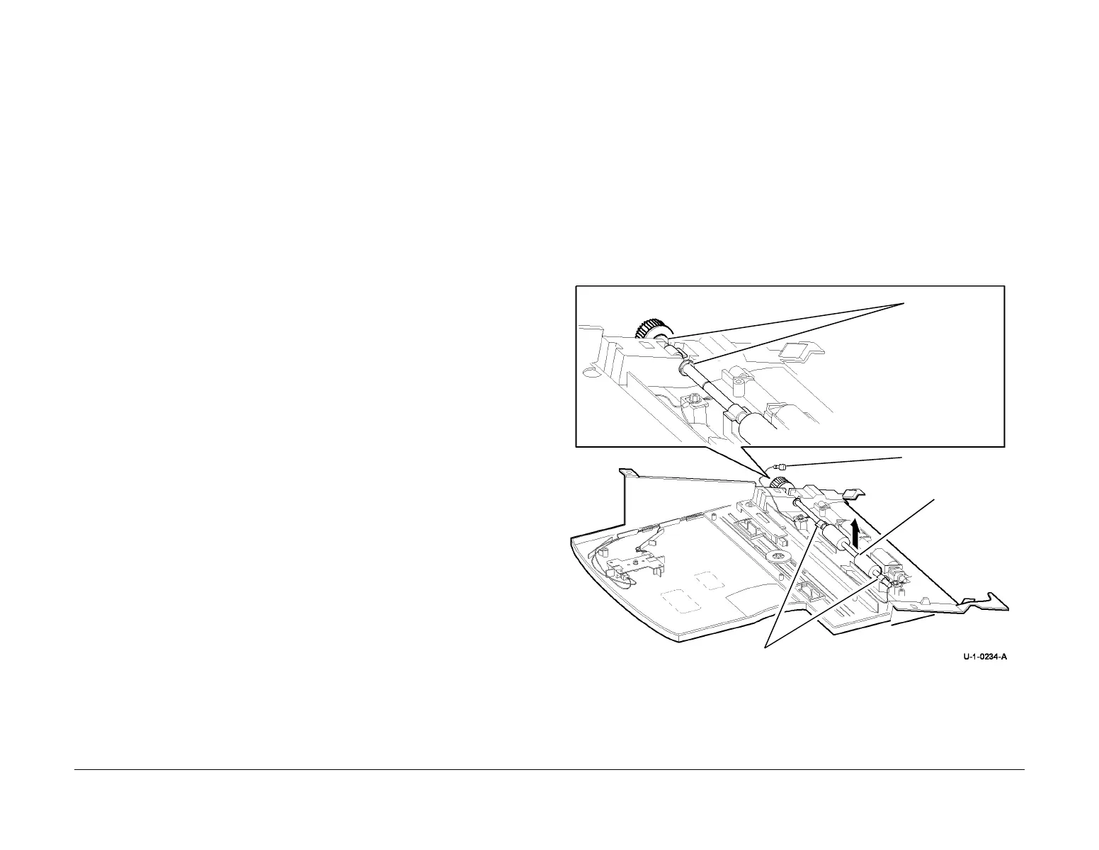
4. Remove the exit roll assembly, Figure 1.
Figure 1 Exit roll assembly removal
Replacement
1. Place the exit roll assembly in position, ensure that the plastic washers are located on
either side of the housing, refer to Figure 1.
2. Press the retaining clips into their locating holes, refer to Figure 1.
3. The remainder of the replacement procedure is the reverse of the removal procedure.
Ground harness.
See CAUTION.
1
lift the exit roll
assembly to
remove.
Plastic washers.
Retaining clips
 Loading...


