February 2013
6-52
ColorQube® 9303 Family
GP 15
General Procedures/Information
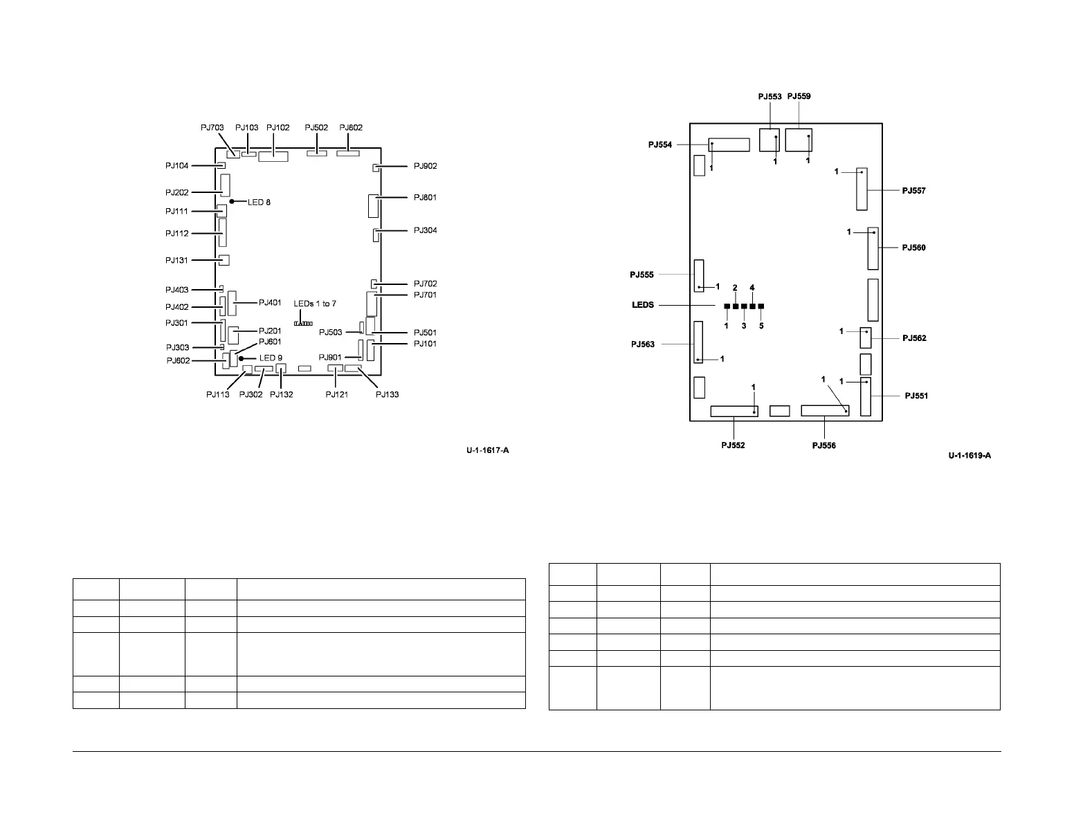
Refer to Figure 10 for the location of the LED’s on the HVF PWB.
Figure 10 HVF PWB
HVF Booklet Maker PWB
Table 11 indicates the state of the LED’s on a good working HVF booklet maker PWB, PL
12.175 Item 10.
Refer to Figure 11 for the location of the LED’s on the PWB.
Figure 11 HVF booklet maker PWB
Scanner PWB
Table 12 indicates the state of the LED’s on a good scanner PWB, PL 62.16 Item 8.
Table 11 HVF BM PWB
LED ID LED colour Status Description
LED 1 Red Off Steady indicates a fault or other abnormal status
LED 2 Yellow Flashing Flashing indicates software operating in normal mode
LED 3 Orange On +24V present and tri-folder door and top cover interlocks
closed. Or without tri-folder interlock cheat in PJ553 and
logic cheat in PJ563.
LED 4 Orange On +24V is within the voltage and current limits
LED 5 Blue On +5V present
Table 12 Scanner PWB
LED ID LED colour Status Description
D13 Red On +24V present
D14 Red On +12 V present
D15 Red On +3.3V present
D16 Red On +5V present
LED 1 Green Flashing Heartbeat, flashes for software operating in normal mode
LED 2 Red Off If there is a hardware reset, e.g. a voltage dip on the 3.3V
power line, the LED will turn on and only switch off when
the software re-initializes.
 Loading...


