February 2013
4-166
ColorQube® 9303 Family
REP 12.30-171
Repairs/Adjustments
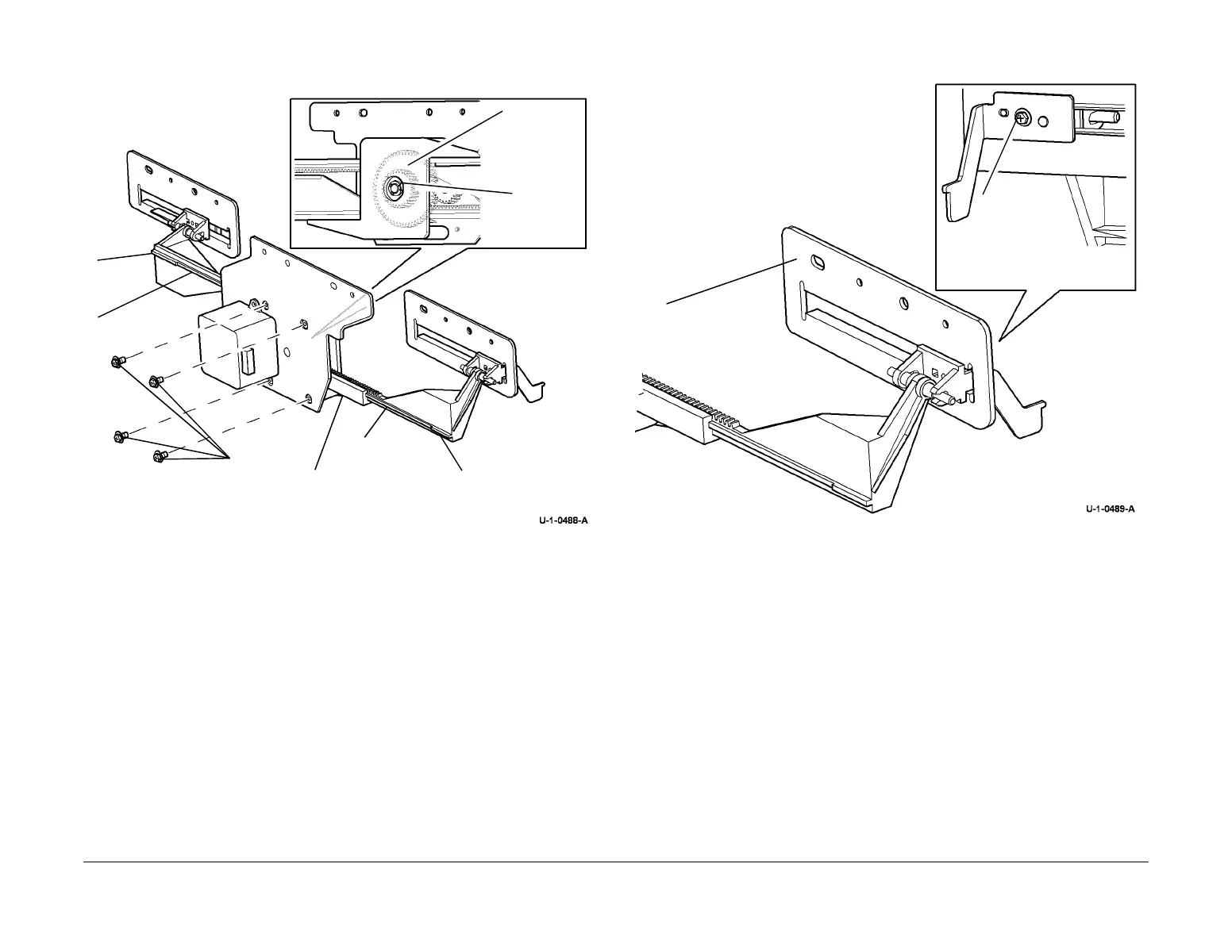
7. Figure 2, remove the front and rear tamper assemblies. Also remove the tamper gear and
tamper motor.
Figure 2 Dismantling the tamper assembly
8. Figure 3, remove the tamper guide plate from each of the tamper assemblies.
Figure 3 Guide plate removal
Replacement
1. If the tamper racks were removed from the BM tamper rack guide, perform the following:
a. Align the guide tabs on both tamper racks with the slots in the BM tamper rack guide.
Refer to Figure 2.
b. Start both tamper racks into the BM tamper rack guide at the same time. Both
tamper racks must engage with the BM tamper gear simultaneously. To check that
the front and rear tampers are correctly aligned, perform the following:
• Fully push in the tampers.
• The distance between the end stop on each tamper and the ends of the BM
tamper rack guide should be equal. Refer to Figure 2.
• If the distances are different by more than 1 mm (0.040 inches). Perform again
step B.
2. Reverse the removal procedure to replace the BM tamper assembly and tamper 1 motor.
3. Perform ADJ 12.5-171 Booklet Tamping.
1
Pull out both tamper
assemblies.
4
Remove
the E-clip.
2
Remove 4
screws.
5
Remove
the gear.
Remove 2 screws, then
remove the motor.
3
Remove the BM
tamper rack guide.
Guide tab
Guide tab
End stop
End
stop
1
Remove the
screw and
tamper finger.
2
Remove the
guide plate.
 Loading...


