Virtex-4 FPGA Configuration User Guide www.xilinx.com 31
UG071 (v1.12) June 2, 2017
Serial Configuration Interface
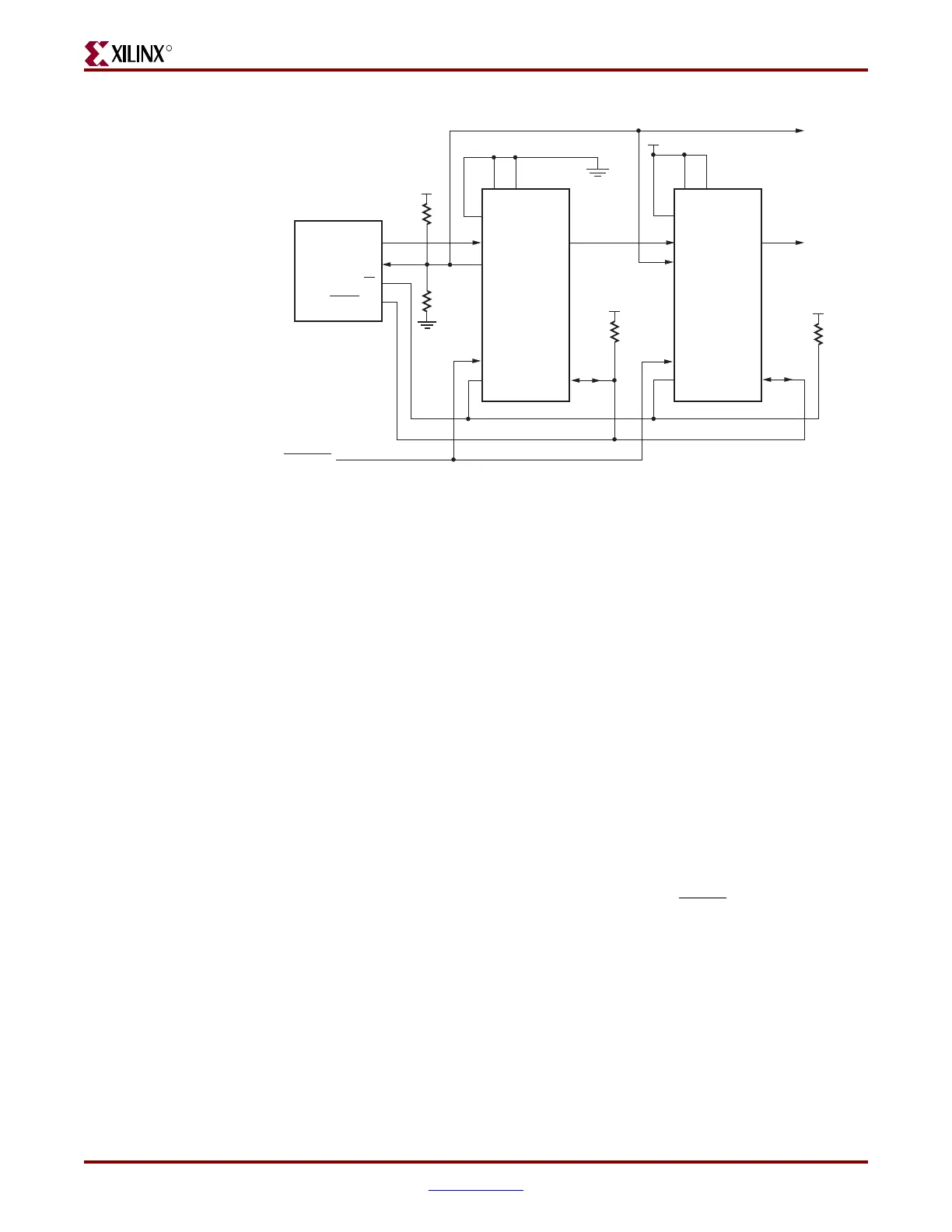
Notes relevant to Figure 2-4:
1. The DONE pin is by default an open-drain output requiring an external pull-up
resistor. A 330Ω pull-up resistor is recommended. For all devices except the last, the
active driver on DONE must be disabled. For the last device in the chain, the active
driver on DONE can be enabled. See “Guidelines and Design Considerations for Serial
Daisy Chains.”
2. The INIT_B pin is a bidirectional, open-drain pin. An external pull-up resistor is
required.
3. The BitGen startup clock setting must be set for CCLK for serial configuration. The
oscillator frequency can be selected in BitGen (default is 4 MHz). Selectable
frequencies are 4, 5, 7, 8, 9, 10, 13, 15, 20, 26, 30, 34, 41, 45, 51, 55, and 60 MHz. Because
the oscillator can vary by ± 50%, select a maximum frequency not to exceed the F
MAX
of the configuration device.
4. The PROM in this diagram represents one or more Xilinx serial PROMs. Multiple serial
PROMs can be cascaded to increase the overall configuration storage capacity.
5. The .bit file must be reformatted into a PROM file before it can be stored on the serial
PROM. Separate bitstream files cannot be concatenated together to form a daisy-chain
bitstream. Refer to the “Generating PROM Files” section.
6. On XC17V00 PROMs, the reset polarity is programmable. RESET
should be set for
active Low when using an XC17V00 device in this setup.
7. The CCLK net requires Thevenin parallel termination. See “Board Layout for
Configuration Clock (CCLK),” page 34.
The first device in a serial daisy chain is the first to be configured. No data is passed onto
the DOUT pin until all the data frames, the start-up command, and CRC check have been
loaded. CRC checks only include the data for the current device, not for any others in the
chain. (See “Cyclic Redundancy Check (Step 7)” in Chapter 1.)
After the first device in the chain finishes configuration and passes its CRC check, it enters
the Start-Up sequence. At the Release DONE pin phase in the Start-Up sequence, the device
Figure 2-4: Master/Slave Serial Mode Daisy Chain Configuration
Virtex-4
Master
Serial
DATA DOUT
INIT_B
DIN
CCLK
PROGRAM_B
DONE
M2
M0 M1
CLK
CE
RESET/OE
PROGRAM
Virtex-4
Slave
Serial
DOUT
INIT_B
DIN
CCLK
PROGRAM_B
DONE
(2)
M2
M0 M1
ug071_17_073007
(1)
Xilinx
Serial PROM
(7)
(7)

 Loading...


