Virtex-4 FPGA Configuration User Guide www.xilinx.com 35
UG071 (v1.12) June 2, 2017
Serial Configuration Interface
Figure 2-7 shows the basic multi-drop flyby topology for one CCLK driver and two CCLK
receivers. The stub at CCLK input 1 has a length constraint.
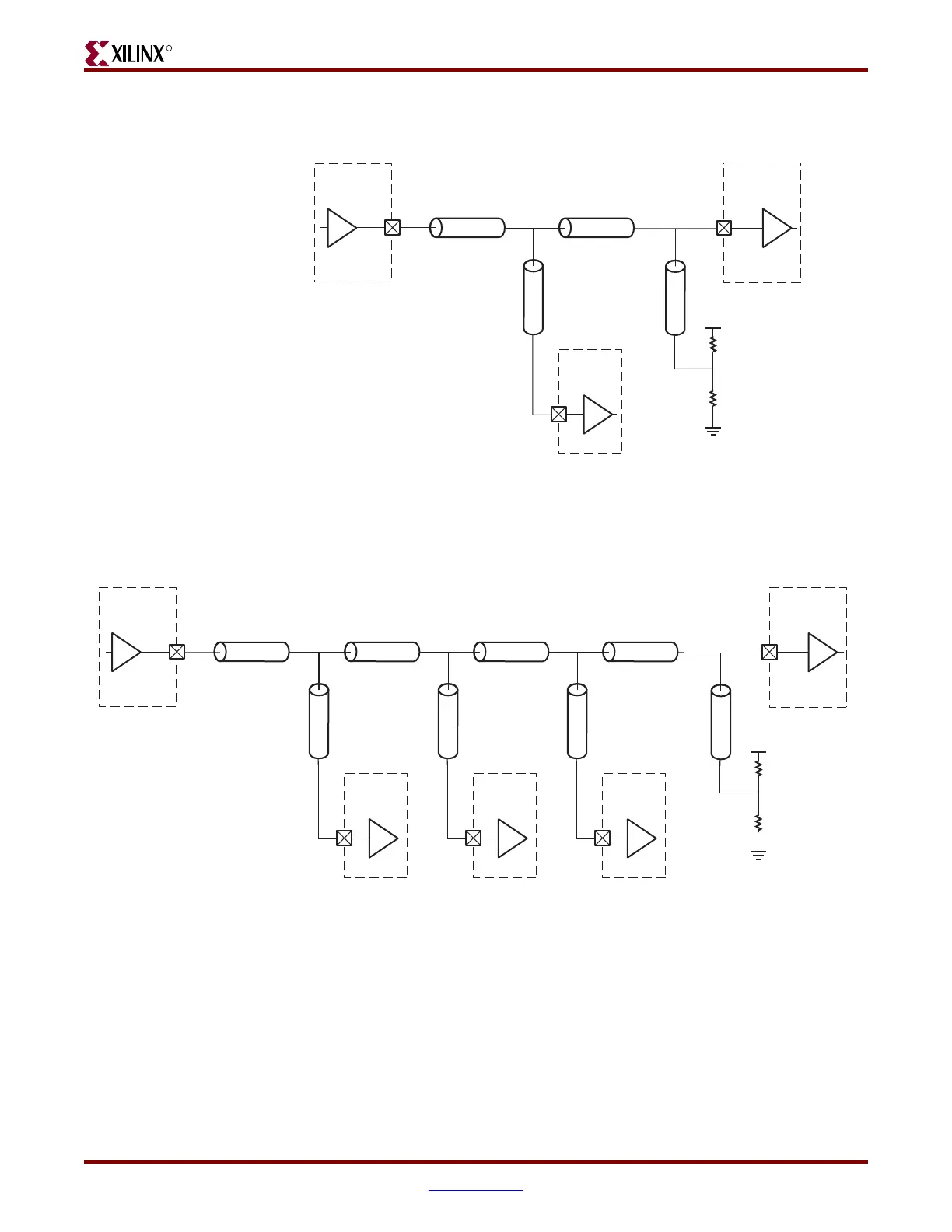
Figure 2-8 shows the multi-drop flyby topology for one CCLK driver and more than two
CCLK receivers (four in this example). All CCLK inputs except input 4 have length
constraints.
Figure 2-7: Multi-Drop: One CCLK Output, Two CCLK Inputs
CCLK
Output
ug071_2_07_072505
Z
0
(50 Ω)
CCLK
Input 2
Z
0
(50 Ω)
CCLK
Input 1
Z
0
(50 Ω)
2 x Z
0
(100 Ω)
2 x Z
0
(100 Ω)
V
CCO_0
Z
0
(50 Ω)
length < 8mm
Figure 2-8: Multi-Drop: One CCLK Output, More Than Two CCLK Inputs
CCLK
Output
Z
0
(50 Ω)
CCLK
Input 4
Z
0
(50 Ω)
2 x Z
0
(100 Ω)
2 x Z
0
(100 Ω)
V
CCO_0
Z
0
(50 Ω)
Z
0
(50 Ω)
CCLK
Input 2
length < 8mm
Z
0
(50 Ω)
Z
0
(50 Ω)
CCLK
Input 3
length < 8mm
Z
0
(50 Ω)
Z
0
(50 Ω)
CCLK
Input 1
length < 8mm
ug071_2_08_072505

 Loading...


