62Y3A11
5-68
1
2
3
4
5
6
7
8
I
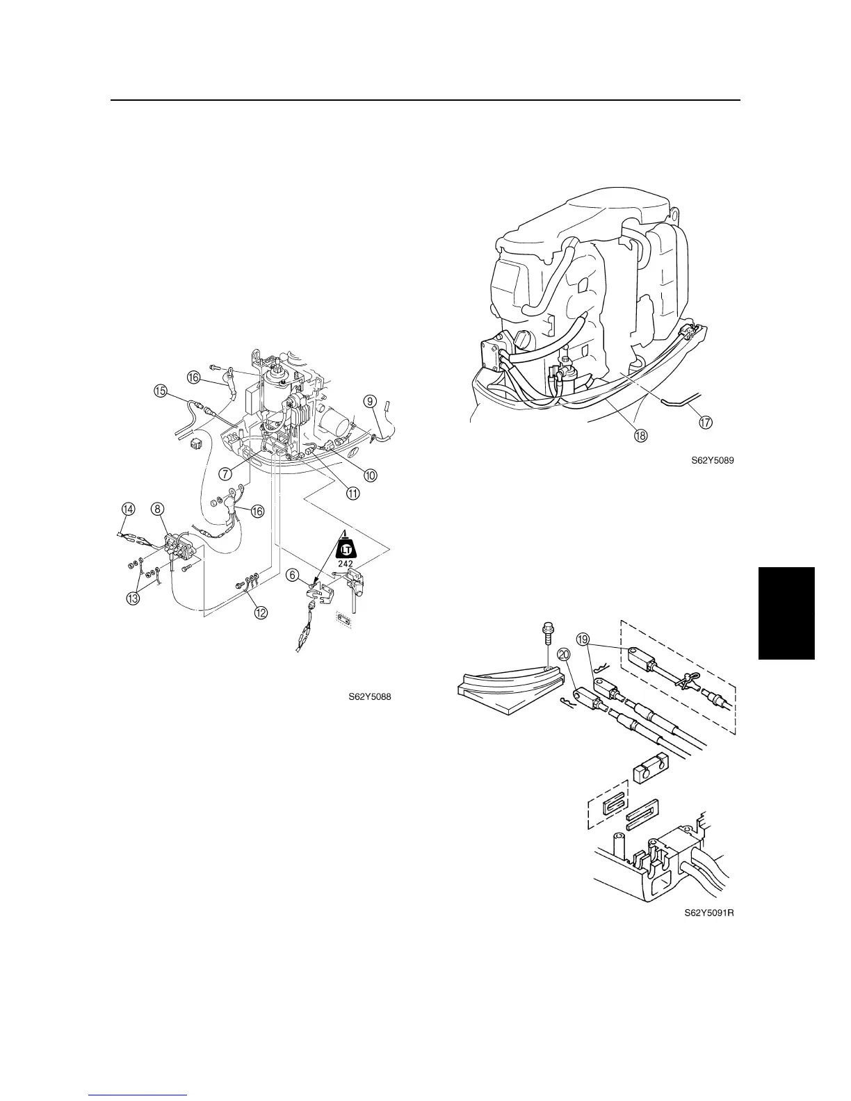
4. Install the shift rod bolts
6
, shift rod
7
and power trim and tilt relay
8
.
5. Connect the flushing hose (models with
flushing device), pilot water hose
9
,
trailer switch coupler
0
(EHT, ET), warn-
ing indicator coupler
A
(EHD, EHT),
ground lead
B
(EHT, ET), PTT motor
leads
C
(EHT, ET), PTT relay leads
D
(EHT, ET), 10-pin coupler
E
, and battery
leads
F
.
6. Connect the throttle link rod
G
and fuel
hose
H
.
7. Connect the shift cable/shift rod
I
and
throttle cable
J
, and then adjust their
lengths. For adjustment procedures, see
Chapter 3, “Checking the throttle cable
operation,” and “Checking the gearshift
operation.”
Cylinder body