62Y3A11
8-26
1
2
3
4
5
6
7
8
I
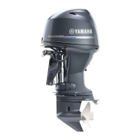
Checking the lighting coil
1. Measure the lighting coil output peak
voltage. Replace the stator coil if below
specification.
WARNING
When checking the peak voltage do not
touch any of the connections of the digital
tester leads.
NOTE:
• Use the peak voltage adaptor with the digi-
tal circuit tester.
• When measuring the peak voltage, set the
selector on the digital circuit tester to the
DC voltage mode
.
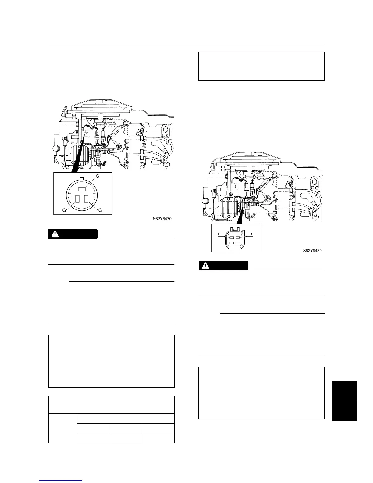
Checking the Rectifier Regulator
1. Measure the Rectifier Regulator output
peak voltage. If below specification, mea-
sure the lighting coil output peak voltage.
Replace the Rectifier Regulator if the out-
put peak voltage of the lighting coil is
above specification.
WARNING
When checking the peak voltage do not
touch any of the connections of the digital
tester leads.
NOTE:
• Use the peak voltage adaptor with the digi-
tal circuit tester.
• When measuring the peak voltage, set the
selector on the digital circuit tester to the
DC voltage mode
.
Digital multimeter: YU-34899-A
Digital circuit tester: 90890-03174
Peak voltage adaptor:
YU-39991 / 90890-03172
Test harness (3 pins):
YB-06770 / 90890-06770
Lighting coil output peak voltage:
Green (G) – Green (G)
r/min
Unloaded
Cranking 1,500 3,500
DC V 11.9 42 127
Lighting coil resistance (use as reference):
Green (G) – Green (G)
1.2–1.8
Ω
at 20 °C (68 °F)
Digital multimeter: YU-34899-A
Digital circuit tester: 90890-03174
Peak voltage adaptor:
YU-39991 / 90890-03172
Test harness (4 pins):
YB-06771 / 90890-06771
Charging system