62Y3A11
6-32
1
2
3
4
5
6
7
8
I
Shimming
NOTE:
• Shimming is not required when assembling
the original lower case and inner parts.
• Shimming is required when assembling the
original inner parts and a new lower case.
• Shimming is required when replacing the
inner parts.
Selecting the pinion shims
1. Calculate the specified value (M0) as
shown in the examples below.
NOTE:
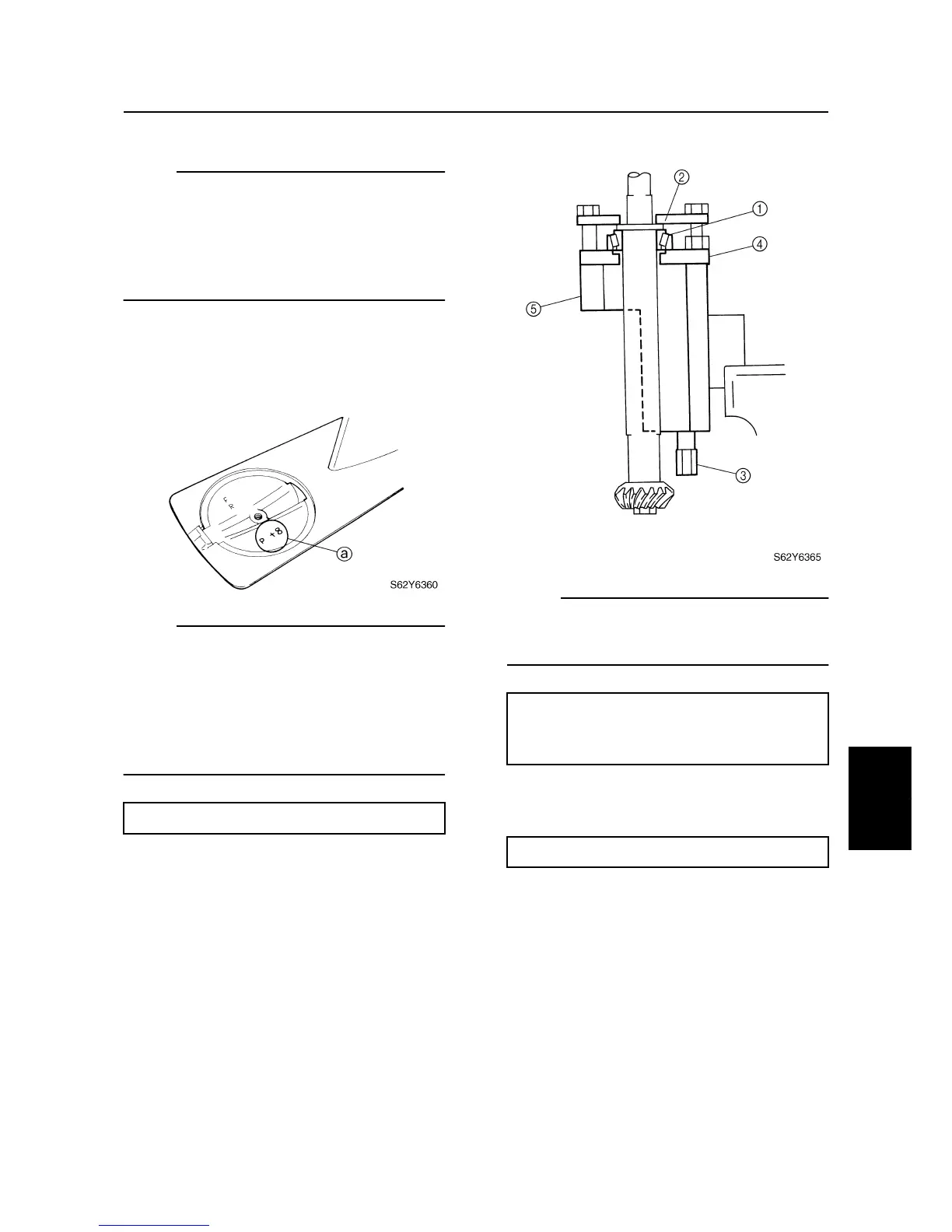
“P” is the deviation of the lower case dimen-
sion from standard. The “P” mark
a
is
stamped on the trim tab mounting surface of
the lower case in 0.01 mm units. If the “P”
mark is unreadable, assume that “P” is zero
and check the backlash when the unit is
assembled.
Example:
If “P” is “+5”, then
M0 = 0.30 + (+5)/100 mm = 0.30 + 0.05 mm
= 0.35 mm
If “P” is “–5”, then
M0 = 0.30 + (–5)/100 mm = 0.30 – 0.05 mm
= 0.25 mm
2. Install the drive shaft and drive shaft
bearing
1
to the shim selecting tools.
3. Attach the clamp
2
to the gauge base
using four bolts of appropriate sizes.
NOTE:
Install the shim selecting tools to the drive
shaft so that the shaft is at the center of the
hole.
4. Install the pinion and pinion nut, and then
tighten the nut to the specified torque.
Specified value (M0) = 0.30 + P/100 mm
Pinion shim selecting tools:
YB-34432-8
3
, YB-34432-10A
4
,
YB-34432-11A
5
, YB-34432-17
2
Pinion nut: 75 N·m (7.5 kgf·m, 54 ft·lb)
Shimming (F50) (for USA and Canada)