62Y3A11
8-16
1
2
3
4
5
6
7
8
I
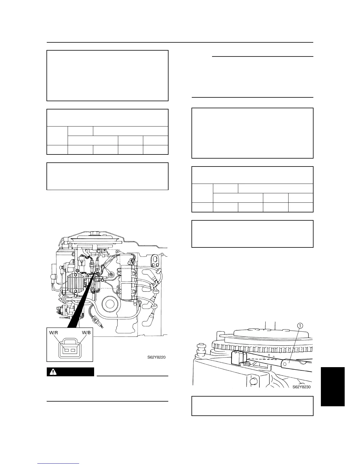
Checking the pulser coil
1. Measure the pulser coil output peak volt-
age. Replace the pulser coil if below
specification.
WARNING
When checking the peak voltage do not
touch any of the connections of the digital
tester leads.
NOTE:
• Use the peak voltage adaptor with the digi-
tal circuit tester.
• When measuring the peak voltage, set the
selector on the digital circuit tester to the
DC voltage mode
.
Checking the pulser coil air gap
1. Turn the flywheel clockwise to align the
projection of the flywheel with the pulser
coil projection.
2. Measure the gap between both projec-
tions with a thickness gauge
1
. Adjust if
out of specification.
Digital multimeter: YU-34899-A
Digital circuit tester: 90890-03174
Peak voltage adaptor:
YU-39991 / 90890-03172
Test harness (2 pins):
YB-06767 / 90890-06767
Charge coil output peak voltage:
Brown (Br) – Blue (L)
r/min
Unloaded
Loaded
Cranking 1,500 3,500
DC V 144 137 169 129
Charge coil resistance (use as reference):
Brown (Br) – Blue (L)
272–408
Ω
at 20 °C (68 °F)
Digital multimeter: YU-34899-A
Digital circuit tester: 90890-03174
Peak voltage adaptor:
YU-39991 / 90890-03172
Test harness (2 pins):
YB-06767 / 90890-06767
Pulser coil output peak voltage:
White/red (W/R) – White/black (W/B)
r/min
Unloaded
Loaded
Cranking 1,500 3,500
DC V 6.3 3.5 7.4 11.2
Pulser coil resistance (use as reference):
White/red (W/R) – White/black (W/B)
396–594
Ω
at 20 °C (68 °F)
Pulser coil air gap:
0.5–1.0 mm (0.020–0.039 in)
Ignition system and Ignition control system