GEN
INFO
General information
1-1
62Y3A11
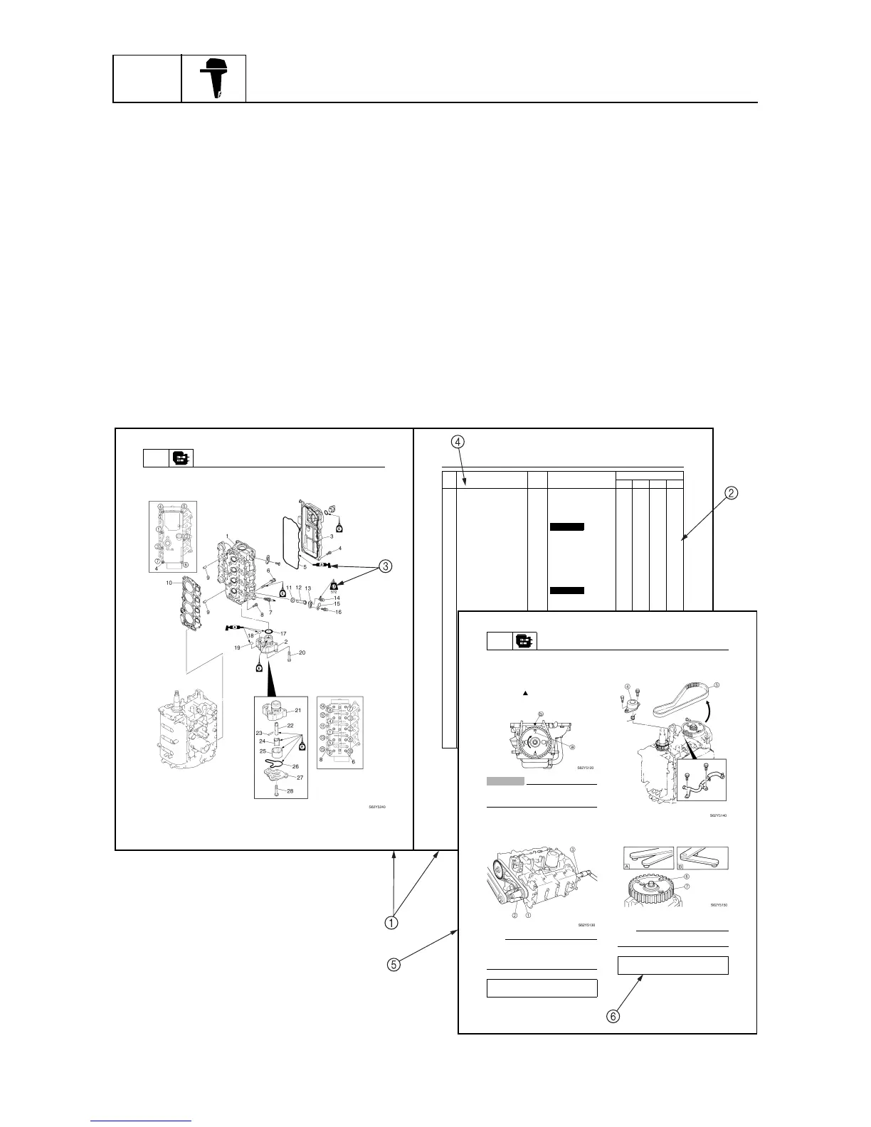
How to use this manual
1
Manual format
The format of this manual has been designed to make service procedures clear and easy to under-
stand. Use the information below as a guide for effective and quality service.
1
Parts are shown and detailed in an exploded diagram and are listed in the components list.
2
Tightening torque specifications are provided in the components list at the beginning of each
section and after a numbered step with tightening instructions.
3
Symbols are used to indicate important aspects of a procedure, such as the grade of lubricant
and lubrication point.
4
The components list consist of parts and part quantities, as well as bolt and screw dimensions.
5
Service points regarding removal, checking, and installation are shown in individual illustrations
to explain the relevant procedure.
6
This service manual has two types of special service tools. Use part numbers that start with “J-”,
“YB-”, “YM-”, “YS-”, “YU-”, “YW-”, or “YX-” for USA and Canada. Use parts numbers that start
with “90890-” for all other countries.
POWR
Power unit
5-35
62Y1A11
Cylinder head
62Y1A11
5-36
5
È
Tightening sequence
No. Part name Q’ty Remarks
Tightening torques
Stage N·mkgf·mft·lb
1 Cylinder head 1
2Oil pump1
3 Cylinder head cover 1
4Bolt 7 M6
×
20 mm
5 Cylinder head cover
gasket
1
Not reusable
6 Bolt 10 M9
×
95 mm 1st
2nd
23
47
2.3
4.7
17
34
7 Spark plug 4 18 1.8 13
8Bolt 5 M6
×
25 mm 1st
2nd
6
12
0.6
1.2
4.3
8.7
9 Dowel pin 2
10 Cylinder head gasket 1
Not reusable
11 Grommet 4
12 Anode 4
13 Cover 4
14 Bolt 4
15 Cover 4
16 Bolt 4
17 O-ring 1
Not reusable
18 O-ring 1
Not reusable
19 O-ring 1
Not reusable
20 Bolt 4 M6
×
40 mm
21 Housing 1
22 Drive shaft 1
23 Pin 1
24 Inner rotor 1
25 Outer rotor 1
26 Gasket 1
Not reusable
27 Cover 1
28 Screw 2 M6
×
20 mm
Cylinder head
POWR
Power unit
5-31
62Y1A11
Removing the timing belt and
sprockets
1. Set the cylinder #1 piston position to
TDC of the compression stroke by align-
ing the “1” mark
a
on the driven sprocket
with the “” mark
b
on the cylinder
head.
CAUTION:
Do not turn the drive sprocket counter-
clockwise, otherwise the valve system
may be damaged.
2. Remove the breather hose and loosen
the drive sprocket nut
1
.
NOTE:
• Use a deep socket
2
(M42) for this proce-
dure.
• Do not turn the camshaft when loosening
the drive sprocket nut.
3. Remove the tensioner
4
and timing belt
5
from the driven sprocket side.
4. Loosen the driven sprocket bolt
6
and
remove the driven sprocket .
È
For USA and Canada
É
For worldwide
NOTE:
Do not turn the camshaft when loosening the
driven sprocket bolt.
Crankshaft holder
3
: YB-06562
Crankshaft holder 18
3
: 90890-06562
Flywheel magnet holder: YB-06139
Flywheel holder: 90890-06522