62Y3A11
1-22
1
2
3
4
5
6
7
8
I
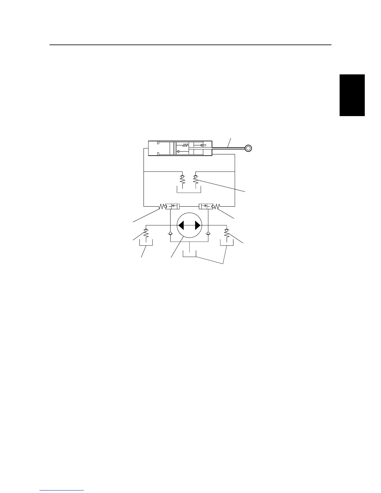
Power trim and tilt
The newly designed power trim and tilt consists of an up-main valve, a down-main valve, an up-
relief valve, a single cylinder, and a single ram, which control both trim and tilt functions.
The power trim and tilt cylinder has been integrated with the gear pump housing, the reservoir tank,
and the power trim and tilt motor in order to achieve a smaller and more compact unit.
Hydraulic system diagram
1
Power trim and tilt cylinder
2
Ram
3
Reservoir
4
Manual valve
5
Down-main valve
6
Down-relief valve
7
Hydraulic pump
8
Up-relief valve
9
Up-main valve
1
2
4
5
6
3
73
8
9
3
S62Y1370
Technical tips