62Y3A11
6-16
1
2
3
4
5
6
7
8
I
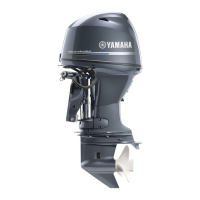
Assembling the propeller shaft
assembly
1. Install the dog clutch as shown.
NOTE:
Install the dog clutch
1
with the “F” mark
a
facing toward the shift plunger.
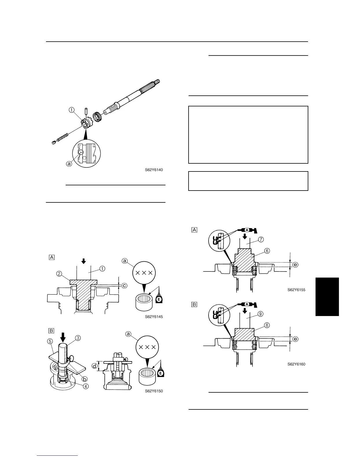
Assembling the propeller shaft
housing
1. Install the needle bearing into the propel-
ler shaft housing to the specified depth.
È
For USA and Canada
É
For worldwide
NOTE:
• Install the needle bearing with the manufac-
ture identification mark
a
facing toward the
oil seal (propeller side).
• Do not strike the driver rod in a manner that
will force the stopper
b
out of place.
2. Apply grease to the new oil seals, and
then install them into the propeller shaft
housing to the specified depth.
È
For USA and Canada
É
For worldwide
NOTE:
Install an oil seal halfway into the propeller
shaft housing, then the other oil seal.
Driver handle
1
: YB-06071
Bearing housing needle bearing installer
2
:
YB-06111
Driver rod SS
3
: 90890-06604
Needle bearing attachment
4
:
90890-06614
Bearing depth plate
5
: 90890-06603
Depth
c
: 3.0–3.5 mm (0.12–0.14 in)
Depth
d
: 23.0–23.5 mm (0.91–0.93 in)
Water pump and propeller shaft housing (F50/F50A)