ELEC
Electrical systems
– +
8-17
62Y3A11
3. Remove the flywheel magnet nut and fly-
wheel magnet.
4. Loosen the pulser coil screws, adjust the
pulser coil
2
position, and then tighten
the screws finger tight.
5. Set the flywheel magnet and then check
the gap again and, if necessary, repeat
steps 3–5.
6. Tighten the pulser coil screws and fly-
wheel magnet nut to the specified
torques.
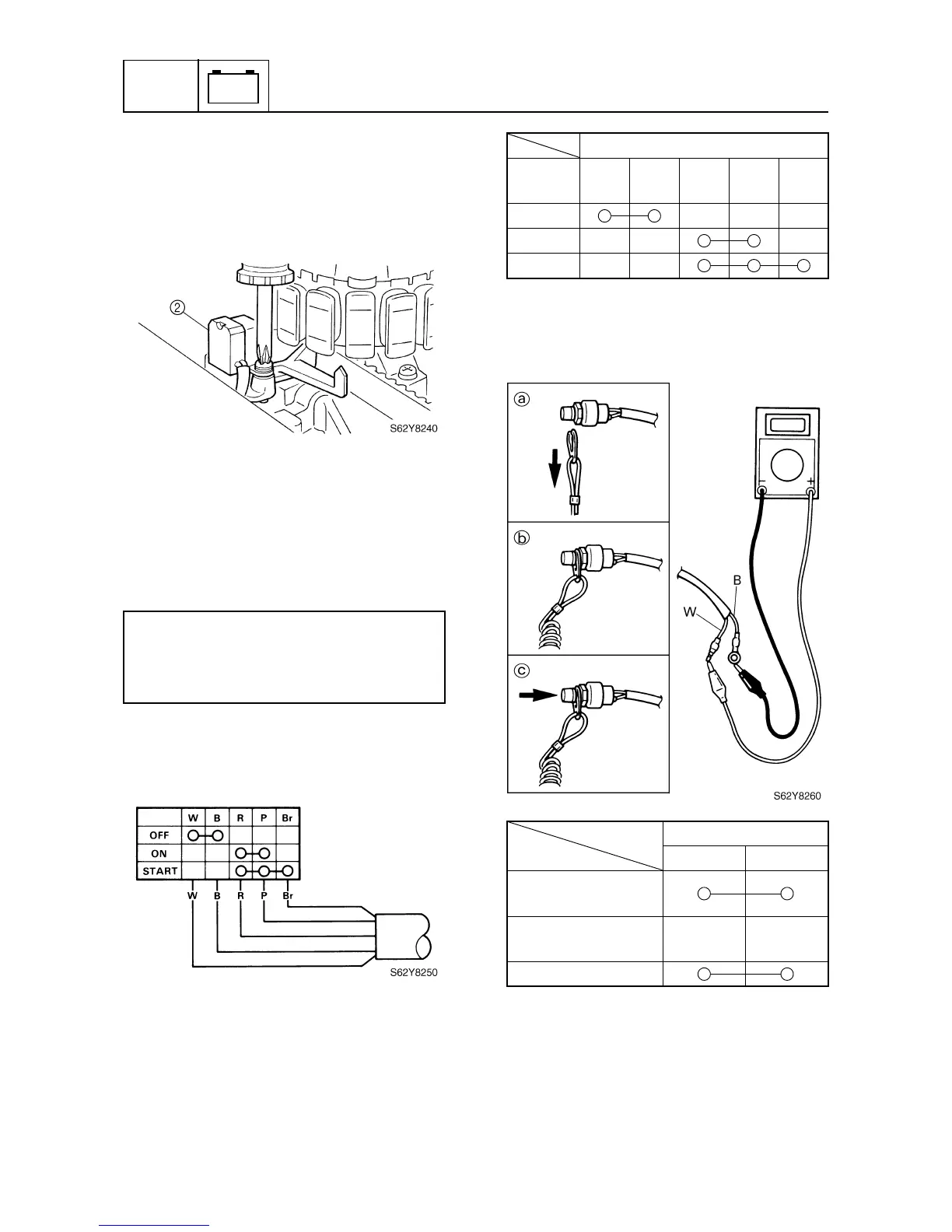
Checking the engine start switch
1. Check the engine start switch for continu-
ity. Replace if there is no continuity.
Checking the engine shut-off switch
1. Check the engine shut-off switch for con-
tinuity. Replace if there is no continuity.
Pulser coil screw:
4 N·m (0.4 kgf·m, 2.9 ft·lb)
Flywheel magnet nut:
160 N·m (16 kgf·m, 116 ft·lb)
Lead color
Switch
position
White
(W)
Black
(B)
Red
(R)
Pink
(P)
Brown
(Br)
OFF
ON
START
Lead color
White (W)
Black (B)
Remove the lock
plate
a
Install the lock
plate
b
Push the button
c