Chapter 7 Reduction and Reversing Gear
_3._I_n_s.;;.p_e_c_ti_on_a_n_d_S_e_r_v_ic_i_n
...
g
________________________
3,4JH3(B)(C)E
mm
Standard
dimensions
Limited
dimensions
Dimensions
2 j KM3A
29.2-29.8
28.1
NOTE : When dismantled, the forward
or
reverse direc-
tion
of
the drive cone must be clearly identified.
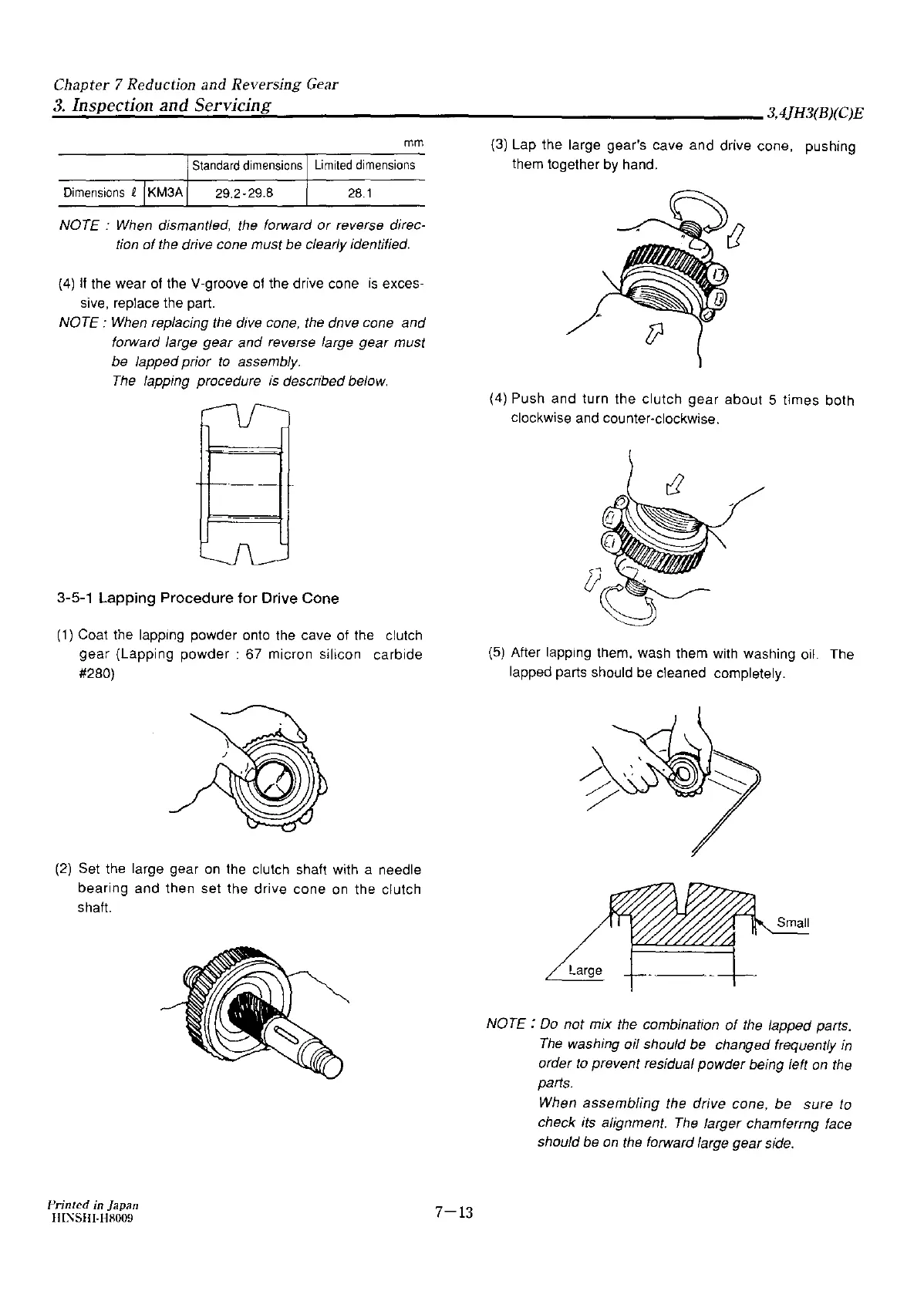
(4) If the wear of the V-groove
of
the drive cone
is
exces-
sive, replace the part.
NOTE :
When
replacing the dive cone, the dnve cone and
forward large gear and reverse large
gear
must
be lapped prior
to
assembly.
The
lapping procedure
is
descnbed below.
3-5-1
Lapping
Procedure
for
Drive Cone
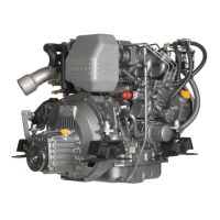
(1) Coat the lapping powder onto the cave of the clutch
gear
(Lapping powder : 67 micron silicon carbide
#280)
(2) Set the large gear
on
the clutch shaft with a needle
bearing and then set the drive cone
on
the clutch
shaft
Printed
in
Japan
l!I~SHI-H8009
7-13
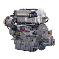
(3)
Lap the large gear's cave and drive cone, pushing
them together
by
hand.
(4) Push and turn the clutch gear about 5 times both
clockwise and counter-clockwise.
(5) After lapping them, wash them with washing oil. The
lapped parts should
be
cleaned completely.
Large
NOTE:
Do
not mix the combination
of
the lapped parts.
The
washing oil should be changed frequently
in
order
to
prevent residual powder being left
on
the
parts.
When assembling the drive cone,
be
sure to
check its alignment.
The
larger chamferrng face
should be
on
the forward large gear side.