Chapter 3 Fuel Injection
Equipment
_2._G_o_ve;;...r_n_o_r
_____________________________
3,4JH3(B)(C)E
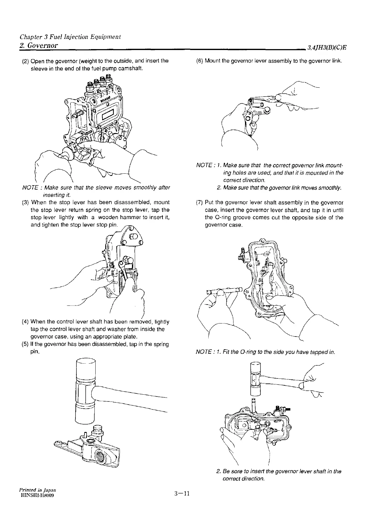
(2)
Open the governor (weight
to
the outside,
and
insert
the
sleeve
in
the end
of
the fuel pump camshaft.
NOTE : Make sure that the sleeve moves smoothly after
inserting
it.
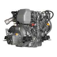
(3)
When the stop lever has been disassembled, mount
the stop lever return spring
on
the stop lever, tap the
stop lever lightly with a wooden hammer
to
insert
it,
and tighten the stop lever stop pin.
)
(4)
When the control lever shaft has been removed, lightly
tap the control lever shaft and washer from inside the
governor case, using
an
appropriate plate.
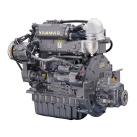
(5)
II
the governor has been disassembled, tap
in
the spring
pin.
Printed
in
Japan
IIINSilI-Jl!l009
3-11
(6)
Mount the governor lever assembly
to
the governor link.
NOTE :
1.
Make sure that the correct governor link mount-
ing holes are used,
and
that it
is
mounted
in
the
correct direction.
2.
Make sure that
the
governor link moves smoothly.
(7)
Put the governor lever shaft assembly
in
the governor
case, insert the governor lever shaft, and tap
it
in
until
the 0-ring groove comes out the opposite side
of
the
governor case.
NOTE:
1.
Fit the 0-ring
to
the side you have tapped
in.
2.
Be sore
to
insert the governor lever shaft
in
the
correct direction.