3.1 Main Circuit Wiring
3-7
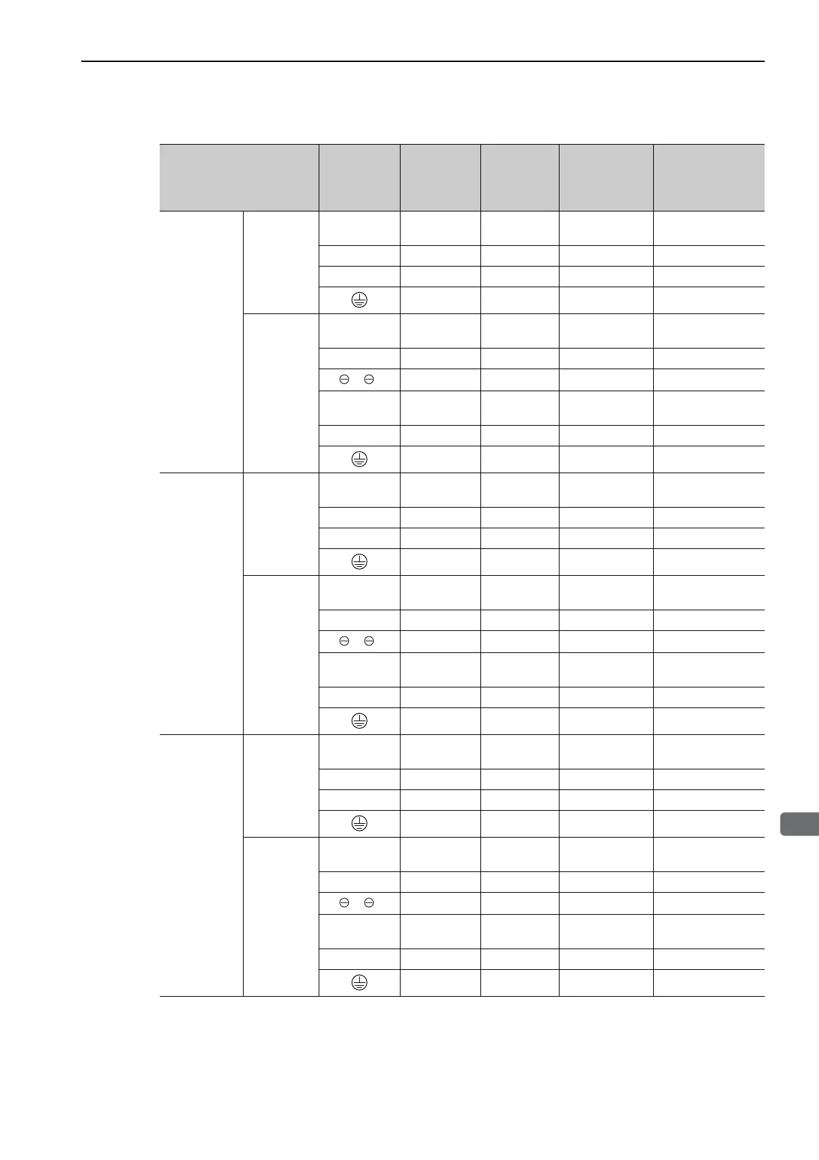
For Three-phase, 400 V
∗1. Use SERVOPACKs and converters in the specified combinations.
∗2. Use the crimp terminals that are recommended by Yaskawa or an equivalent.
Combination of SERVO-
PACK and Converter
*1
Terminal
Symbols
Screw Size
for Terminals
Tightening
Tor qu e
(Nm)
HIV Wire Size
in mm
2
(AWG)
Crimp Terminal
Model
(Made by J.S.T.
Mfg Co., Ltd.)
*2
SGDV-750J
SGDV-
COA3ZDA
SERVO-
PACK
P, N M8 15.0
Bus bar attached
to the converter
–
U, V, W M8 3.0 22 (4) R22-8
DU, DV, DW M6 3.0 3.5 (12) 3.5-6
M8 9.0 to 11.0 22 (4) R22-8
Converter
P, N M8 3.0
Bus bar attached
to the converter
–
L1, L2, L3 M8 3.0 22 (4) R22-8
1, 2
M8 3.0 22 (4) R22-8
CN101
(24 V, 0 V)
–
(Connector)
– 1.25 (16) –
B1, B2 M8 3.0 8 (8) R8-8
M8 9.0 to 11.0 22 (4) R22-8
SGDV-101J
SGDV-
COA5EDA
SERVO-
PACK
P, N M8 15.0
Bus bar attached
to the converter
–
U, V, W M8 3.0 38 (1) R38-8
DU, DV, DW M6 3.0 3.5 (12) 3.5-6
M8 9.0 to 11.0 38 (1) R38-8
Converter
P, N M10 12 to 20
Bus bar attached
to the converter
–
L1, L2, L3 M10 12 to 20 38 (1) R38-10
1, 2
M10 12 to 20 38 (1) R38-10
CN101
(24 V, 0 V)
–
(Connector)
– 1.25 (16) –
B1, B2 M10 12 to 20 8 (8) R8-10
M8 9.0 to 11.0 38 (1) R38-8
SGDV-131J
SGDV-
COA5EDA
SERVO-
PACK
P, N M10 12 to 20
Bus bar attached
to the converter
–
U, V, W M10 30.0 60 (2/0) R60-10
DU, DV, DW M6 3.0 3.5 (12) 3.5-6
M8 9.0 to 11.0 60 (2/0) R60-8
Converter
P, CN M10 12 to 20
Bus bar attached
to the converter
–
L1, L2, L3 M10 12 to 20 60 (2/0) R60-10
1, 2
M10 12 to 20 60 (2/0) R60-10
CN101
(24 V, 0 V)
–
(Connector)
– 1.25 (16) –
B1, B2 M10 12 to 20 14 (6) R14-10
M8 9.0 to 11.0 60 (2/0) R60-8

 Loading...


