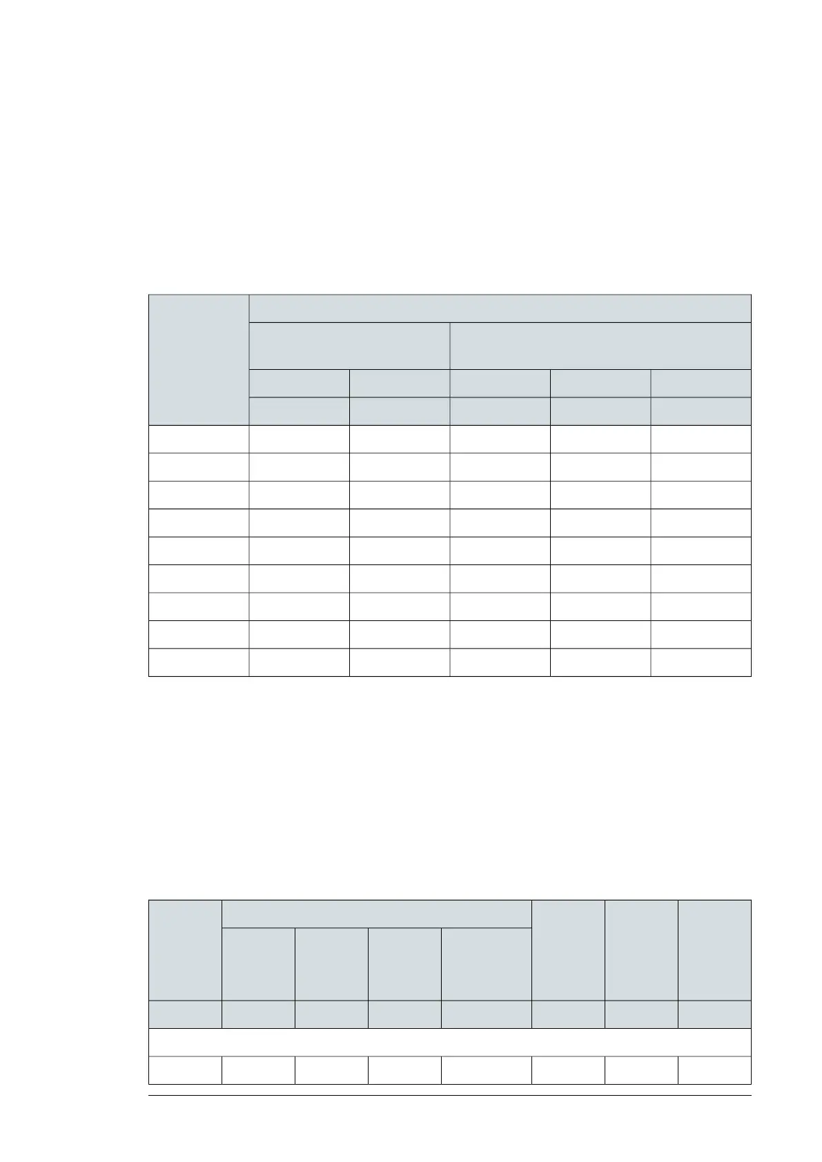
Symbols
IP20
Height of front sideH1
Height of back side (without cable connecting box)H2
WidthW
DepthD
Free spaceFrame size
Vertical installation
Side by side
Vertical installation
Independent
IntervalBelowAboveBelowAbove
mmmmmmmmmm
075757575R0
075757575R1
075757575R2
0200200200200R3
0200200200200R4
0300200300200R5
0300200300200R6
0300200300200R7
0300200300200R8
See the figures in section Checking the installation site (page 40).
Thermal losses, cooling data and noise
The air flow direction is from bottom to top.
The table below specifies the heat dissipation in the main circuit at nominal load and in the
control circuit with minimum load (I/O, options and panel not in use) and maximum load (all
digital inputs and relays in the ON state, and the panel, fieldbus and fan in use). The total
heat dissipation is the sum of the heat dissipation in the main and control circuits. Use the
maximum heat dissipation when designing cabinet or electrical room cooling needs.
Frame sizeNoiseAir flowThermal lossesDesig.
ACQ80-04-
Main circuit
and control
circuit Max.
load
Control cir-
cuit Max.
load
Control cir-
cuit Min.
load
Main cir-
cuit nomin-
al I
1N
, I
N
dB(A)m
3
/hWWWW
3 phases U
N
= 400V (380…480V)
R063.10574490.3350kW75-4
Technical data 121

 Loading...


