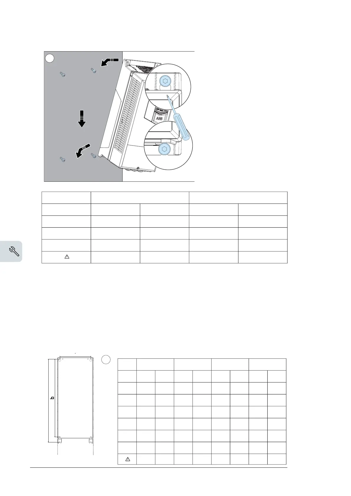
Mechanical installation 49
Installing the drive vertically, frame size R3...R4
1. Mark the hole locations with the mounting template included in the package. Do
not leave the mounting template behind the drive. The drive dimensions and hole
locations are also shown in the drawings, see chapter Dimension drawings on
page 149.
2. Drill the mounting holes.
3. Start the screws or bolts into the mounting holes.
2
3
R3 R4
mm in mm in
a 160 6.30 160 6.30
b 473 18.62 619 24.37
Weight kg lb kg lb
14.86 32.77 23.0 50.72
1
R4R3
inmminmm
6.301606.30160a
24.3761918.62473b
lbkglbkgWeight
41.8919.032.8414.9
Mechanical installation 49
Installing the drive vertically, frame size R3...R4
1. Mark the hole locations with the mounting template included in the package. Do
not leave the mounting template behind the drive. The drive dimensions and hole
locations are also shown in the drawings, see chapter Dimension drawings on
page 149.
2. Drill the mounting holes.
3. Start the screws or bolts into the mounting holes.
2
3
R3 R4
mm in mm in
a 160 6.30 160 6.30
b 473 18.62 619 24.37
Weight kg lb kg lb
14.86 32.77 23.0 50.72
1
■ Installing the drive vertically, frames size R5…R8
1. Mark the punch positions for the six mounting holes with the mounting template included
in the package. Do not leave the mounting template under the drive.
The drive dimensions and hole locations are also shown in the drawings, see chapter
Dimension drawings (page 137).
Note:
You can use only two screws instead of four to attach the lower part of the drive
R8R7R6R5
inmminmminmminmm
10.42639.72458.42136.3160a
25.965822.958320.953122.9581b
27.670124.562322.557124.1612c
11.830011.830011.830011.8300d
7.92007.92007.92007.9200e
lbkglbkglbkglbkg
152.1269.0119.0554.093.4842.462.3928.3
Mechanical installation 49
Installing the drive vertically, frame size R3...R4
1. Mark the hole locations with the mounting template included in the package. Do
not leave the mounting template behind the drive. The drive dimensions and hole
locations are also shown in the drawings, see chapter Dimension drawings on
page 149.
2. Drill the mounting holes.
3. Start the screws or bolts into the mounting holes.
2
3
R3 R4
mm in mm in
a 160 6.30 160 6.30
b 473 18.62 619 24.37
Weight kg lb kg lb
14.86 32.77 23.0 50.72
1
50 Mechanical installation
Installing the drive vertically, frames size R5…R8
1. Mark the punch positions for the six mounting holes with the mounting template
included in the package. Do not leave the mounting template under the drive.
The drive dimensions and hole locations are also shown in the drawings, see
chapter Dimension drawings on page 149.
Note: You can use only two screws instead of four to attach the lower part of the
drive.
2. Drill the mounting holes.
3. Start the screws or bolts into the mounting holes.
4. Position the drive onto the screws on the wall. Lift the drive with another person
as it is heavy.
5. Tighten the screws in the wall securely.
R5 R6 R7 R8
mm in mm in mm in mm in
a 612 24.1 571 22.5 623 24.5 701 27.6
b 581 22.9 531 20.9 583 22.9 658 25.9
c 160 6.3 213 8.4 245 9.7 263 10.4
d 300 11.8 300 11.8 300 11.8 300 11.8
e 200 7.9 200 7.9 200 7.9 200 7.9
kg lb kg lb kg lb kg lb
28 62 45 99 55 121 70 154
48 Mechanical installation

 Loading...


