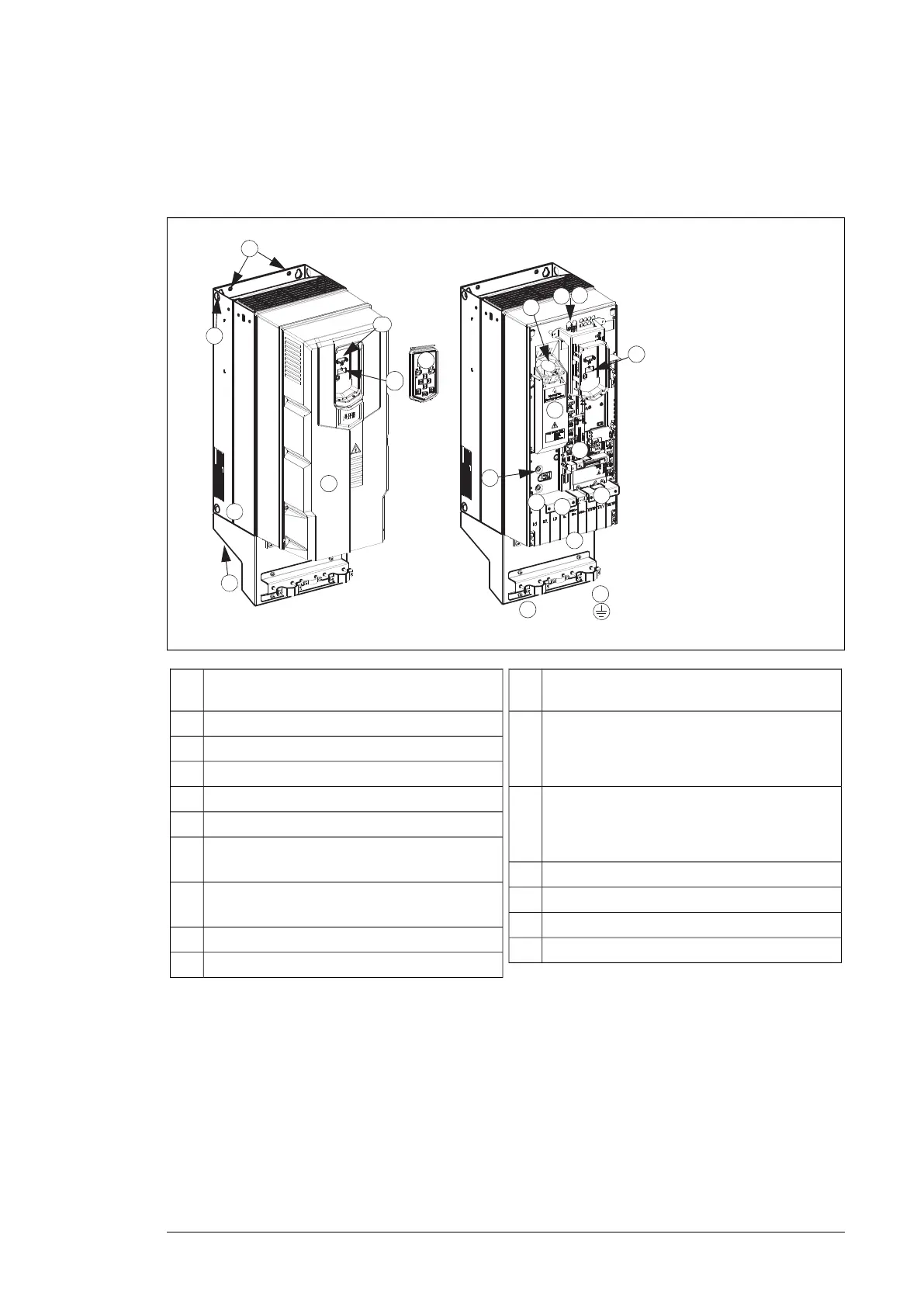
■ Frame R4…R8
The layout of a frame R6 drive is presented below. The frame sizes R7…R8 is similar but
have a different structure.
2
3
4
5
6
7
8
11
12
13
10
10
3
16
15
1
9
12
PE
17
14
1
Voltage dependent resistor ground screw (VAR),
arranged below the control tray.
11
Two EMC filter ground screws, one arranged
below the control tray bracket and the other ar-
ranged on the left and above the protective cov-
er.
12
Protective cover. Below the protective cover: in-
put voltage connection (L1, L2, L3), motor con-
nection (T1/U, T2/V, T3/W) and DC connection
(UDC+, UDC-).
13
PE connection (power line)14
Earthing connection (motor)15
A primary fan16
Auxiliary fan17
Installation point (2 points on the top and 2 points
on the bottom of the frame body)
1
Cover plate2
Lifting hole3
Basic control panel4
Control panel connection5
CCA-01 interface6
For LED of normal power supply and failure, see
section LEDs (page 108).
7
I/O connection. See section External control
connection terminals, frames R6…R8 (page 32).
8
Cable bundle installation position of I/O cable9
Mechanical support clamp of I/O cable10
Overview of power and control connections
The logical diagram below shows the power connections and control interfaces of the drive.
Operation principle and hardware description 29

 Loading...


