Mechanical installation 39
Mechanical installation
Contents of this chapter
The chapter tells how to check the installation site, unpack, check the delivery and
install the drive mechanically.
Safety
WARNING!
• Frames R5…R8:
Lift the drive with a lifting device. Use the lifting eyes of the
drive. Do not tilt the drive. The drive is heavy and its center of gravity is high.
An overturning drive can cause physical injury.
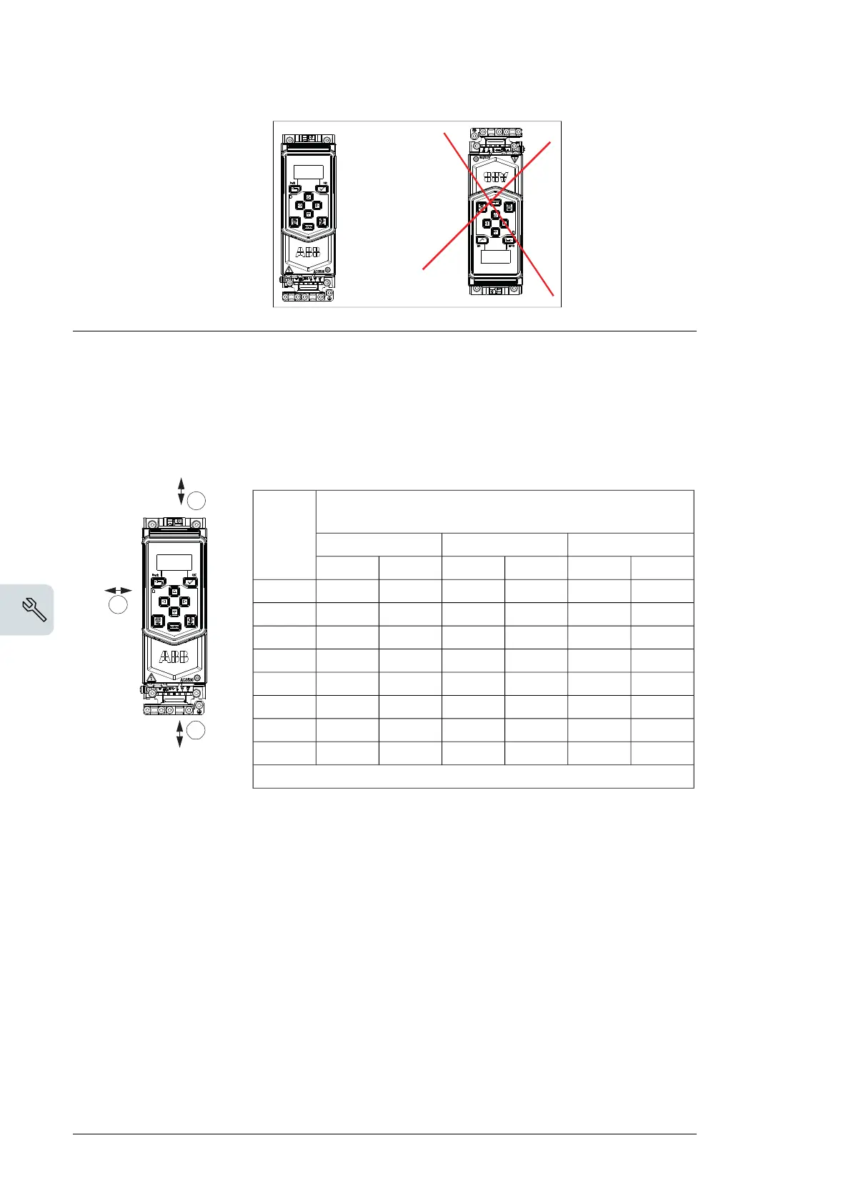
• Do not install the drive upside down. This can cause damage to the equipment.
Checking the installation site
The drive must be placed in a cabinet and installed on the wall. Drives of frame sizes R0...R2
have two installation method as follows:
• Vertically alone
Vertical installation
Free space
Frame
Size
Beside (c)Below (b)Above (a)
inmminmminmm
5.91507.92001.230R0
5.91507.92001.230R1
5.91507.92001.230R2
5.91507.92002.153R3
5.91507.92002.153R4
5.915011.83006.1155R6
5.915011.83006.1155R7
5.915011.83006.1155R8
.
40 Mechanical installation
Checking the installation site
The drive must be placed in a cabinet and installed on the wall. Drives of frame sizes
R0...R2 have two installation method as follows:
• Vertically alone
• Vertically side by side
a
b
c
Frame
Size
Vertical installation
Free space
Above (a) Below (b)
Beside (c)
mm in mm in mm in
R0 30 1.2 200 7.9 150 5.9
R1 30 1.2 200 7.9 150 5.9
R2 30 1.2 200 7.9 150 5.9
R3 53 2.1 200 7.9 150 5.9
R4 53 2.1 200 7.9 150 5.9
R6 155 6.1 300 11.8 150 5.9
R7 155 6.1 300 11.8 150 5.9
R8 155 6.1 300 11.8 150 5.9
.
Frame
size
Vertical installation side by side -
Free space
Above (a) Below (b)
Between (c)
mm in mm in mm in
R0 753753 0 0
R1 753753 0 0
R2 753753 0 0
R3 200 7.9 200 7.9 0 0
R4 200 7.9 200 7.9 0 0
R5 200 7.9 200 11.8 0 0
R6 200 7.9 300 11.8 0 0
R7 200 7.9 300 11.8 0 0
R8 200 7.9 300 11.8 0 0
R8 200 7.9 300 11.8 0 0
3AXD10000561047.xls
a
b
a
b
c= 0
40 Mechanical installation

 Loading...


