■ Connection procedure: frames R0…R2
WARNING! WARNING!
If the drive is connected on an IT (ungrounded) system, make sure that the EMC
Filter and Varistor (VAR) is disconnected. See EMC filter (page 66).
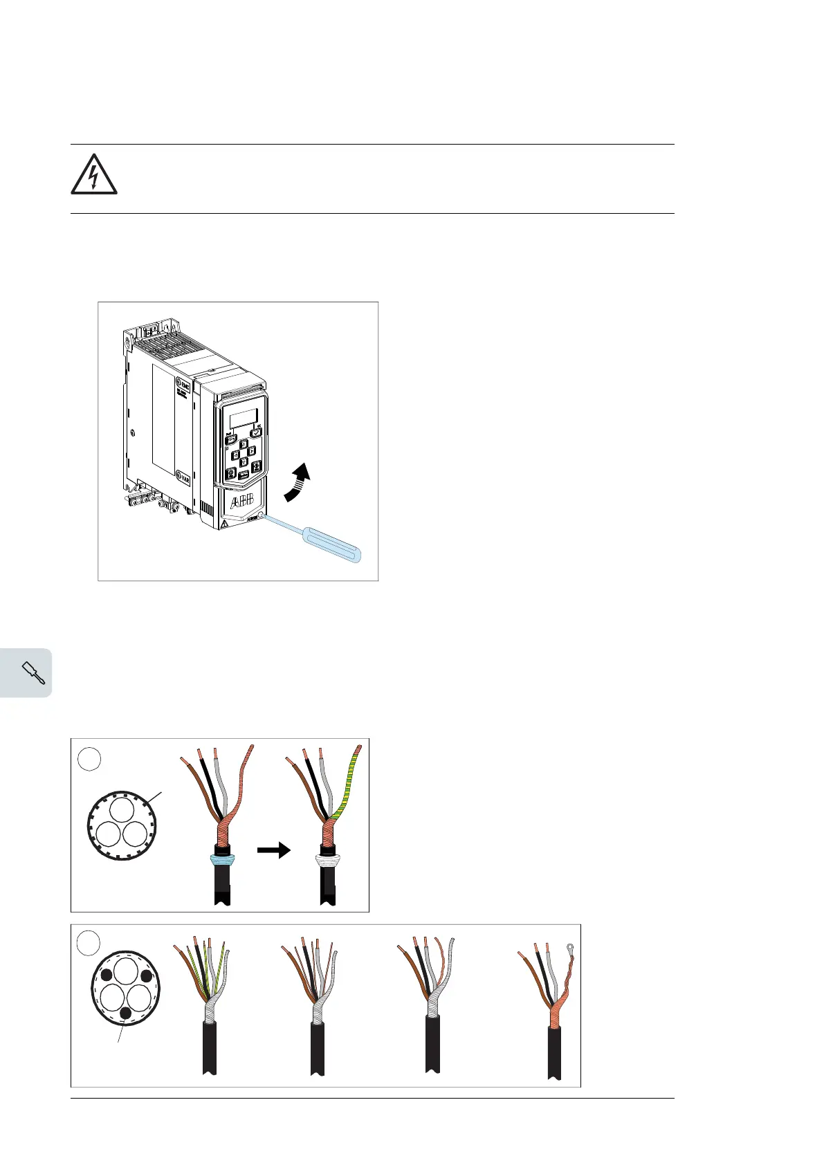
1. Remove the front cover as follows:
• Loosen the retaining screw with a screwdriver (1a).
• Lift the cover from the bottom outwards (1b).
Motor cable
2. Prepare the ends of the cable as illustrated in the figure. Two different motor cable types
are shown in the figures (2a.and 2b).
Note:
The bare shield will be grounded 360 degrees.
78 Electrical installation
Connection procedure, frames R0…R2
1. Remove the front cover as follows:
• Loosen the retaining screw with a screwdriver (1a).
• Lift the cover from the bottom outwards (1b).
Warning! If the drive is connected on an IT (ungrounded) system, make sure
that the EMC Filter and Varistor (VAR) is disconnected. See page 71.
Motor cable
2. Prepare the ends of the cable as illustrated in the figure. Two different motor cable
types are shown in the figures (2a.and 2b).
Note: The bare shield will be grounded 360 degrees.
72 Electrical installation

 Loading...


