Note:
• Leave the other ends of the control cable shields unconnected or ground them indirectly
via a high-frequency capacitor with a few nanofarads, eg, 3.3 nF / 630 V. The shield
can also be grounded directly at both ends if they are in the same ground line with no
significant voltage drop between the end points.
• Keep any signal wire pairs twisted as close to the terminals as possible. Twisting the
wire with its return wire reduces disturbances caused by inductive coupling.
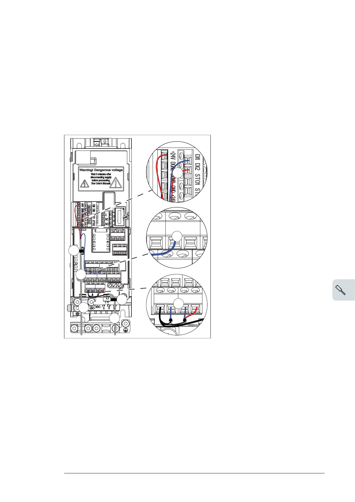
■ R0...R2
100 Electrical installation
9. Route the cable as shown in the figures on pages 100 (R0…R2 and R3...R5)
and101 (R6…R8).
10. Connect the conductors to the appropriate terminals of the control board and
tighten to 0.5…0.6 N·m (0.4 lbf·ft).
11. Tie all control cables to the provided cable tie mounts.
Note:
• Leave the other ends of the control cable shields unconnected or ground them
indirectly via a high-frequency capacitor with a few nanofarads, eg, 3.3 nF / 630 V.
The shield can also be grounded directly at both ends if they are in the same
ground line with no significant voltage drop between the end points.
• Keep any signal wire pairs twisted as close to the terminals as possible. Twisting
the wire with its return wire reduces disturbances caused by inductive coupling.
R3...R5R0…R2
9
11
11
3
5
6
8
9
7
10
R0…R2: 0.5…0.6 N·m (0.4 lbf·ft)
R3: 0.5…0.6 N·m (0.4 lbf·ft)
3
4
5
6
7
8
9
9
4
8
5
6
Electrical installation 91

 Loading...


