• Vertically side by side
Vertical installation side by side -
Free space
Frame
Size
Between (c)Below (b)Above (a)
inmminmminmm
00375375R0
00375375R1
00375375R2
007.92007.9200R3
007.92007.9200R4
0011.82007.9200R5
0011.83007.9200R6
0011.83007.9200R7
0011.83007.9200R8
0011.83007.9200R8
40 Mechanical installation
Checking the installation site
The drive must be placed in a cabinet and installed on the wall. Drives of frame sizes
R0...R2 have two installation method as follows:
• Vertically alone
• Vertically side by side
a
b
c
Frame
Size
Vertical installation
Free space
Above (a) Below (b)
Beside (c)
mm in mm in mm in
R0 30 1.2 200 7.9 150 5.9
R1 30 1.2 200 7.9 150 5.9
R2 30 1.2 200 7.9 150 5.9
R3 53 2.1 200 7.9 150 5.9
R4 53 2.1 200 7.9 150 5.9
R6 155 6.1 300 11.8 150 5.9
R7 155 6.1 300 11.8 150 5.9
R8 155 6.1 300 11.8 150 5.9
.
Frame
size
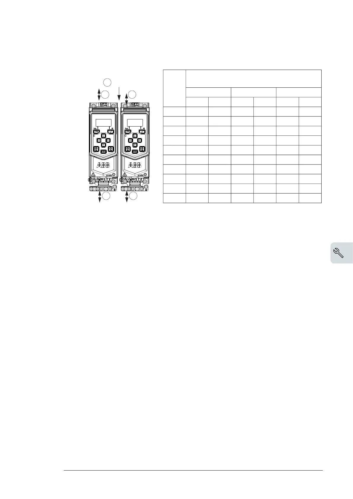
Vertical installation side by side -
Free space
Above (a) Below (b)
Between (c)
mm in mm in mm in
R0 753753 0 0
R1 753753 0 0
R2 753753 0 0
R3 200 7.9 200 7.9 0 0
R4 200 7.9 200 7.9 0 0
R5 200 7.9 200 11.8 0 0
R6 200 7.9 300 11.8 0 0
R7 200 7.9 300 11.8 0 0
R8 200 7.9 300 11.8 0 0
R8 200 7.9 300 11.8 0 0
3AXD10000561047.xls
a
b
a
b
c= 0
3AXD10000651180.xls A
Check the installation site according to the requirements below:
• The installation site is sufficiently ventilated or cooled to remove heat from the drives.
See section Thermal losses, cooling data and noise (page 121).
•
The operation conditions of the drive meet the specifications given in section Ambient
conditions (page 131).
• The wall is as close to vertical as possible, of non-flammable material and strong enough
to carry the weight of the drive, see section Circuit breakers (page 119).
• The floor/material below the installation is non-flammable.
• There is enough free space above and below the drive to enable cooling air flow, service
and maintenance, See the required free space tables for each of the different mounting
alignments in Checking the installation site (page 40) (or Dimensions, weights and free
space requirements (page 120)).
Required tools
To install the drive mechanically, you need the following tools:
• Drill with suitable bits.
• Screwdriver and/or wrench with a set of suitable bits (as appropriate for the installation
hardware used).
• Tape measure, if you are not using the provided mounting template.
Moving the drive
Frames R5…R8: Move the transport package by pallet truck to the installation site.
Mechanical installation 41

 Loading...


