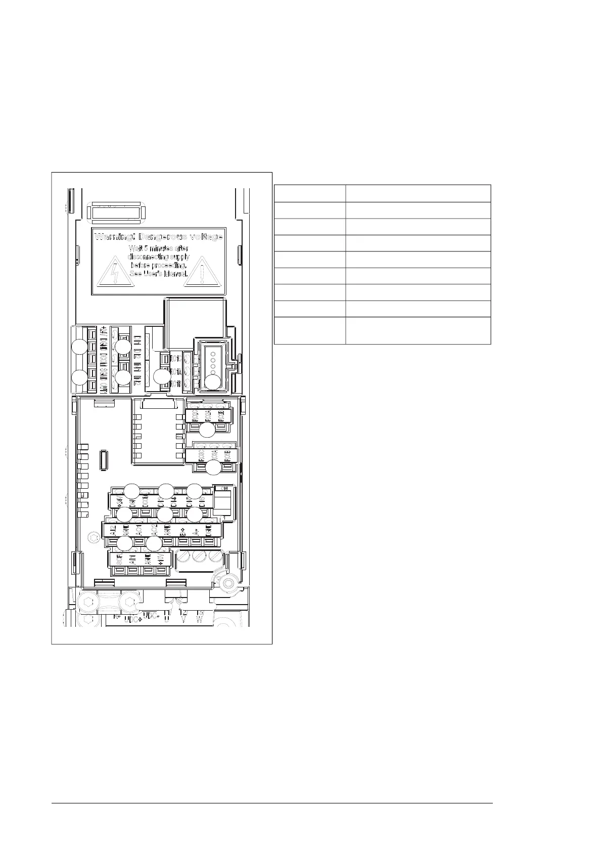
■ External control connecting terminal, Frame size R0…R2
The figure below explains the external control connecting terminal layout of Frame size R0.
Layout of the external control connection terminals is identical in frames R1…R2 but the
location of the control board with the terminals is different in frames R3.
R0...R2
Description
Analog input and outputX1 A…D
Auxiliary voltage outputX2
Digital signal inputX3 A…C
Safety torque cancellationX4 A…B
Modbus built-in fieldbusX5
Relay 1 outputX6…X8
+24V DC voltage outputX11
The interface is used for CCA-01
adapter configuration
1
X1A
X1B
X1C X1D X5
X11 X3B X3C
X8
X7
X
2
X4A
X3A
X4B
X
6
1
30 Operation principle and hardware description

 Loading...


