BIO-01 I/O extension module 157
Electrical installation
Refer to Electrical installation on page 55. If you configure the inputs, set up the
wiring accordingly. The BIO-01 module has removable spring clamp terminals. Use
ferrules on the multistranded cables before assembly.
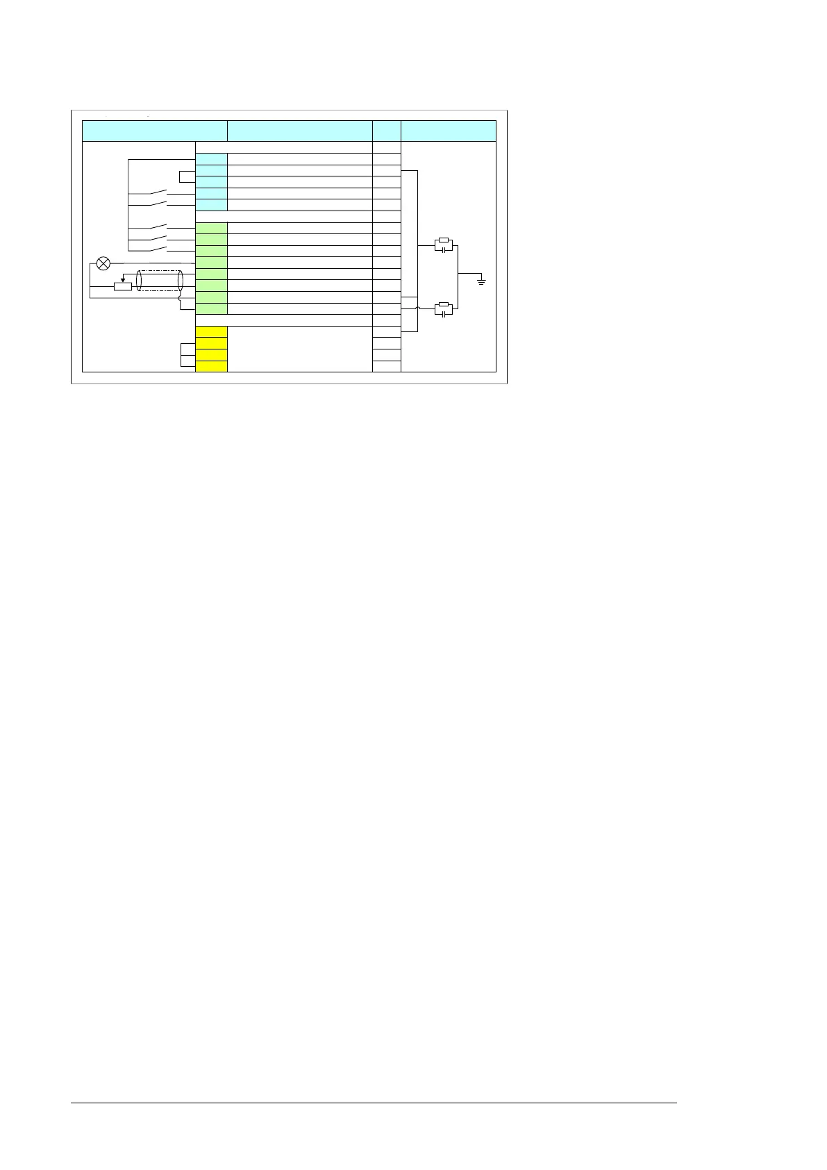
Sample wiring with the ABB standard macro:
Start-up
The BIO-01 module is automatically identified by the drive firmware. To configure the
inputs refer to the ACS480 firmware manual (3AXD50000047399 [English]).
Terminals
External sample connection
Description Base
unit
Internal connection
Aux. voltage output and prog. digital input
+24V Aux. output +24 V DC, max. 200 mA X
DGND Aux. voltage output common X
DCOM Digital input common for all X
DI1 Stop (0)/Start (1) X
DI2 Forward (0)/Reverse (1) X
Digital and analog I/O extension BIO-01
DI3 Constant frequency/speed selection
DI4 Constant frequency/speed selection
DI5 Ramp set 1 (0)/Ramp set 2 (1)
DO1 Not configured
AI1 Output frequency/speed ref: 0...10 V
+10V Ref. voltage +10 V DC (max. 10 mA)
GND Analog circuit common / DO common
SCR Signal cable shield / DO screen
Safe torque off (STO)
SGND Safe torque off. Factory connection.
Both circuits must be closed for the
drive to start.
X
IN1 X
IN2 X
OUT1 X
(3AXD50000170654[English].

 Loading...


