• Connect the phase conductors of the cable to the L1, L2 and L3 terminals.
80 Electrical installation
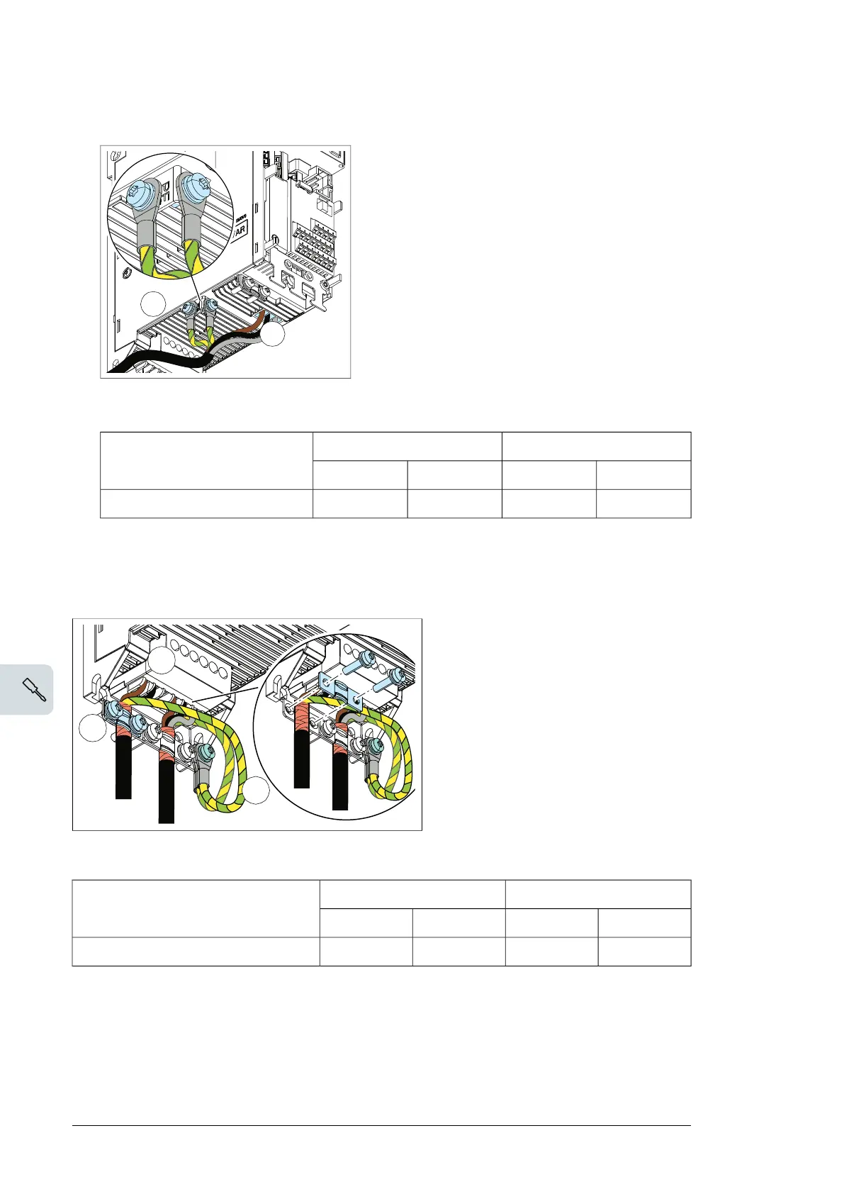
5. Connect the input power cable as follows:
• Connect the twisted shield of the cable to the grounding terminal (5a).
• Connect the phase conductors of the cable to the L1, L2 and L3 terminals.
• Tighten the screws to the torque given below:
6. Connect the braking resistor cable as the motor cable in step 4.
7. Ground the shield 360 degrees (6a).
8. Connect the twisted shield to the grounding terminal (6b) and the conductors to
the R+ and R- terminals (6c).
9. Tighten the screws to the torque given below.
Frame size R0…R1 R2
N·m lbf·ft N·m lbf·ft
L1. L2. L3 0.5…0.6 0.4 1.2…1.5 0.9…1.1
Frame size R0…R1 R2
N·m lbf·ft N·m lbf·ft
R+. R- 0.5…0.6 0.4 1.2…1.5 0.9…1.1
5b
5a
6a
6b
6c
• Tighten the screws to the torque given below:
R2R0…R1Frame size
lbf·ftN·mlbf·ftN·m
0.9…1.11.2…1.50.40.5…0.6L1, L2, L3
7. Ground the shield 360 degrees (6a).
8. Connect the twisted shield to the grounding terminal (6b) and the PV input terminals to
UDC+ and UDC- (6c).
80 Electrical installation
5. Connect the input power cable as follows:
• Connect the twisted shield of the cable to the grounding terminal (5a).
• Connect the phase conductors of the cable to the L1, L2 and L3 terminals.
• Tighten the screws to the torque given below:
6. Connect the braking resistor cable as the motor cable in step 4.
7. Ground the shield 360 degrees (6a).
8. Connect the twisted shield to the grounding terminal (6b) and the conductors to
the R+ and R- terminals (6c).
9. Tighten the screws to the torque given below.
Frame size R0…R1 R2
N·m lbf·ft N·m lbf·ft
L1. L2. L3 0.5…0.6 0.4 1.2…1.5 0.9…1.1
Frame size R0…R1 R2
N·m lbf·ft N·m lbf·ft
R+. R- 0.5…0.6 0.4 1.2…1.5 0.9…1.1
5b
5a
6a
6b
6c
9. Tighten the screws to the torque given below.
R2R0…R1Frame size
lbf·ftN·mlbf·ftN·m
0.9…1.11.2…1.50.40.5…0.6UDC+, UDC-
Finalization
10. Ground the motor cable shield at the motor end. For minimum radio frequency
interference, ground the motor cable shield 360 degrees at the lead-through of the motor
terminal box
74 Electrical installation

 Loading...


