3. Connect the motor cable as follows:
• Ground the shield 360 degrees by tightening the clamp of the power cable grounding
shelf onto the stripped part of the cable (3a).
• Connect the twisted shield of the cable to the grounding terminal (3b).
• Connect the phase conductors of the cable to the terminals of T1/U, T2/V and T3/W.
Electrical installation 79
3. Connect the motor cable as follows:
• Ground the shield 360 degrees by tightening the clamp of the power cable
grounding shelf onto the stripped part of the cable (3a).
• Connect the twisted shield of the cable to the grounding terminal (3b).
• Connect the phase conductors of the cable to the terminals of T1/U, T2/V and
T3/W.
• Tighten the screws to the torque given below.
Input power cable
4. Prepare the ends of the cable as illustrated in the figure.
Note: The bare shield will be grounded 360 degrees. Mark the pigtail made from
the shield as a PE conductor with yellow-and-green color.
Frame size R0…R1 R2
N·m lbf·ft N·m lbf·ft
T1/U. T2/V. T3/W 0.5…0.6 0.4 1.2…1.5 0.9…1.1
3b
3c
3a
PE
PE
• Tighten the screws to the torque given below.
R2R0…R1Frame size
lbf·ftN·mlbf·ftN·m
0.9…1.11.2…1.50.40.5…0.6T1/U. T2/V. T3/W
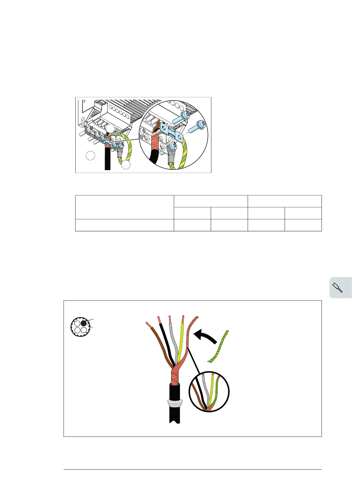
Input power cable
4. Prepare the ends of the cable as illustrated in the figure.
Note:
The bare shield will be grounded 360 degrees. Mark the pigtail made from the shield as a
PE conductor with yellow-and-green color
5. Connect the input power cable as follows:
• Connect the twisted shield of the cable to the grounding terminal (5a).
Electrical installation 73

 Loading...


