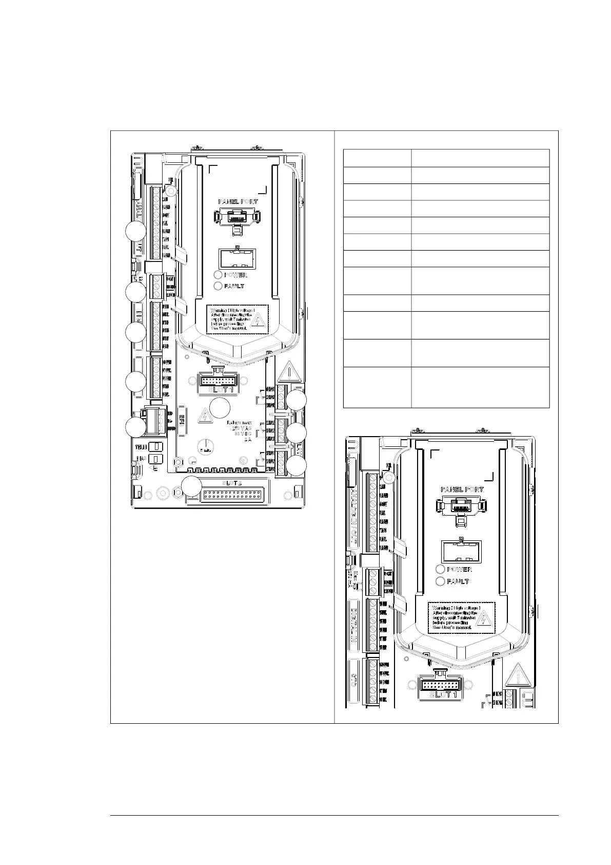
■ External control connecting terminal, Frame size R3...R5
The figure below explains the external control connecting terminal layout of Frame size R3.
Description
Analog input and outputX1
Auxiliary voltage outputX2
Digital inputX3
Safety torque cancellationX4
Modbus built-in fieldbusX5
Relay output 1...Relay output 3X6…X8
Option slot 1 (fieldbus adapter
module)
X13
Option slot 2 (not used)X14
Panel port (control panel connec-
tion)
1
The interface is used for CCA-01
adapter configuration
2
For LED of normal power supply
and failure, see section
LEDs (page 108).
3
Operation principle and hardware description 31

 Loading...


