4. Position the drive onto the screws on the wall. Tighten the screws in the wall securely.
48 Mechanical installation
4. Position the drive onto the screws on the wall. Tighten the screws in the wall
securely.
3
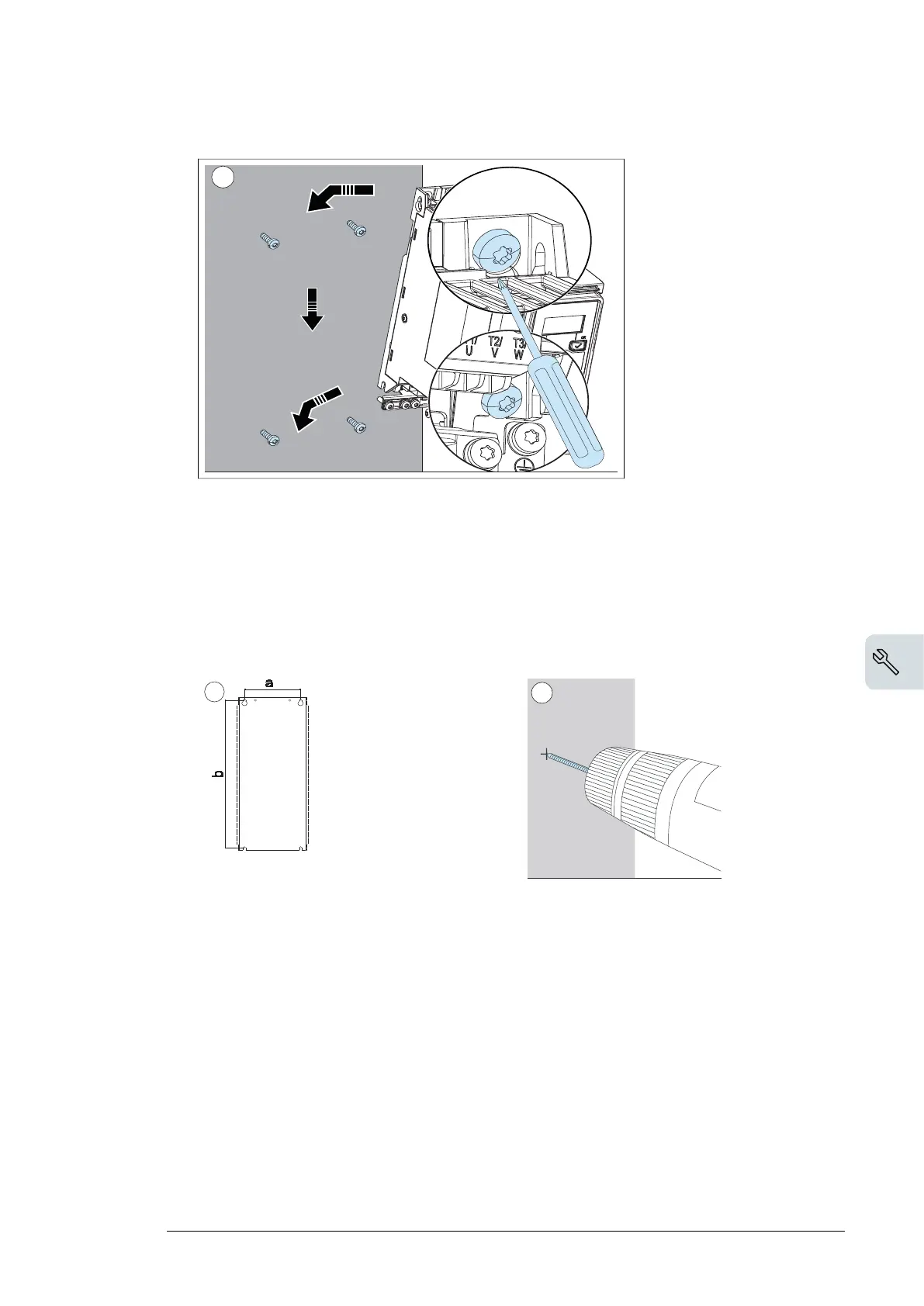
■ Installing the drive vertically, frame size R3...R4
1. Mark the hole locations with the mounting template included in the package. Do not
leave the mounting template behind the drive. The drive dimensions and hole locations
are also shown in the drawings, see chapter Dimension drawings (page 137).
2. Drill the mounting holes.
3. Start the screws or bolts into the mounting holes.
Mechanical installation 49
Installing the drive vertically, frame size R3...R4
1. Mark the hole locations with the mounting template included in the package. Do
not leave the mounting template behind the drive. The drive dimensions and hole
locations are also shown in the drawings, see chapter Dimension drawings on
page 149.
2. Drill the mounting holes.
3. Start the screws or bolts into the mounting holes.
2
3
R3 R4
mm in mm in
a 160 6.30 160 6.30
b 473 18.62 619 24.37
Weight kg lb kg lb
14.86 32.77 23.0 50.72
Mechanical installation 47
Installing the drive
Installing the drive vertically, frames size R0…R2
The figures show frame R0 as an example.
1. Mark the hole locations with the mounting template included in the package. Do
not leave the mounting template behind the drive. The drive dimensions and hole
locations are also shown in the drawings, see chapter Dimension drawings on
page 149.
Note: You can also adopt guide rail installation.
2. Drill the mounting holes.
3. Insert anchors or plugs into the holes and start the screws or bolts into the
anchors or plugs.
R0 R1 R2
mm in mm in mm in
a 50 1.97 75 2.95 148 5.83
b 191 7.52 191 7.52 191 7.52
Weight kg lb kg lb kg lb
4.47 9.86 4.57 10.08 7.54 16.63
2
3
×4
R0…R2: M5
×4
1
×4
Mechanical installation 47

 Loading...


