• Connect the twisted shield of the cable to the grounding terminal (4b).
• Connect the phase conductors of the cable to the T1/U, T2/V and T3/W terminals.
• Tighten the screws to the torque given below:
R4R3Frame size
lbf·ftN·mlbf·ftN·m
3.04.01.8…3.32.5…4.5T1/U. T2/V. T3/W.
Electrical installation 83
3. Connect the motor cable as follows:
If the power cable is temporarily removed from the grounding shelf, connect the
motor and input power cables except the 360 degree grounding, and then reinstall
the grounding shelf.
• Ground the shield 360 degrees by tightening the clamp of the power cable
grounding shelf onto the stripped part of the cable (4a).
• Connect the twisted shield of the cable to the grounding terminal (4b).
• Connect the phase conductors of the cable to the T1/U, T2/V and T3/W terminals.
• Tighten the screws to the torque given below:
Notes
• The screws are of different length. Install them at the correct locations.
• After reinstalling the grounding shelf, you can make the 360 degree grounding for
the cables.
Input power cable
4. Prepare the ends of the cable as illustrated in the figure.
Note: The bare shield will be grounded 360 degrees. Mark the pigtail made from the
shield as a PE conductor with yellow-and-green color.
Frame size
R3
R4
N·m lbf·ft N·m lbf·ft
T1/U. T2/V. T3/W. 2.5…4.5 1.8…3.3 4.0 3.0
4c
4b
4a
PE
PE
Note:
• The screws are of different length. Install them at correct locations.
• After reinstalling the grounding shelf, you can make the 360 degree grounding for the
cables.
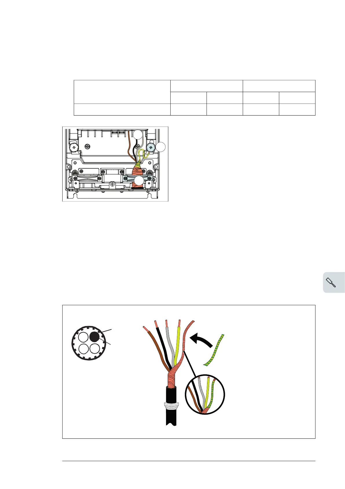
Input power cable
4. Prepare the ends of the cable as illustrated in the figure.
Note:
The bare shield is grounded 360 degrees. Mark the pigtail made from the shield as a PE
conductor with yellow-and-green color.
5. Connect the input power cable as follows:
Electrical installation 77

 Loading...


