Before you start the work, stop the drive and do the steps in section Electrical safety
precautions (page 14).
Front option slot 1
By default, RIIO-01 module is provided in ACS560 standard R0...R2 drives. You can remove
the RIIO-01 module and can install BIO-01 and/or fieldbus adapter module (+fxxx). If you
are installing any of the fieldbus module, see section Routing the cables for suitable connector
types.
For information on BIO-01 option, see BIO-01 I/O extension module (page 163).
Note:
BIO-01 module is applicable only for R0...R2 frame sizes.
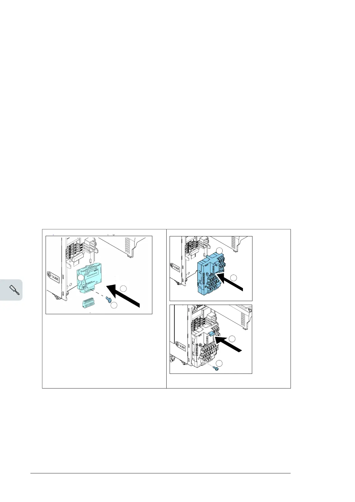
To install RIIO-01, BIO-01 or/and fieldbus module, perform the following steps
1.
Remove the front cover(s). See section Connection procedure: frames
R0…R2 (page 72).
If you have the BIO-01 option module, you can add a fieldbus option module on top of
it. For more information see BIO-01 I/O extension module (page 163).
2. For RIIO-01, pull the plastic locking tab of the optional module that you want to install.
3. Align the module with the option module slot in the front of the drive.
4. Push the option module into position.
70 Electrical installation
If you have the BIO-01 option module, you can add a fieldbus option module on
top of it.
2. Pull the plastic locking tab of the option module up.
3. Carefully align the option module with the
option module slot in the front of the drive.
4. Fully push the option module into
position.
5. Push the plastic locking tab down until it
locks.
6. Tighten the locking screw.
7. Connect the applicable control cables
according to Connecting the control
cables on page 62.
RIIO-01
132 Electrical installation
Installing option modules
Note: In US deliveries, options are already installed at the factory.
Note: If you will install the FPBA
-01 module, see section FPBA-01 PROFIBUS DP
adapter module connectors on page 77 for suitable connector types.
Mechanical installation of option modules
See section Overview of power and control connections page 34 for the available
slots for each module. Install the option modules as follows:
WARNING! Obey the instructions in chapter Safety instructions on page 13. If
you ignore them, injury or death, or damage to the equipment can occur.
Note: Slot 2 in frames R1…R5 is at U
DC
potential. You must disconnect power
supplies before installing or removing an I/O extension module.
Stop the drive and do the steps in section Precautions before electrical work on page
16 before you start the work.
1. Remove the front cover(s) if not already removed. See page 97 (R1…R4), page
105 (R5) or page 63 (R6…R9).
The figures for frames R1…R5 (page 133) and R6…R9 (page 135) show an example
of installing option modules.
4
3
BIO-01
5. For RIIO-01, push the plastic locking tab down until it locks.
6. Tighten the locking screw.
Note:
The optional fieldbus module can also be installed on top of the BIO-01 module. See
BIO-01 I/O extension module (page 163).
7.
For BIO-01, connect the applicable control cables. See Electrical installation (page 165).
94 Electrical installation

 Loading...


