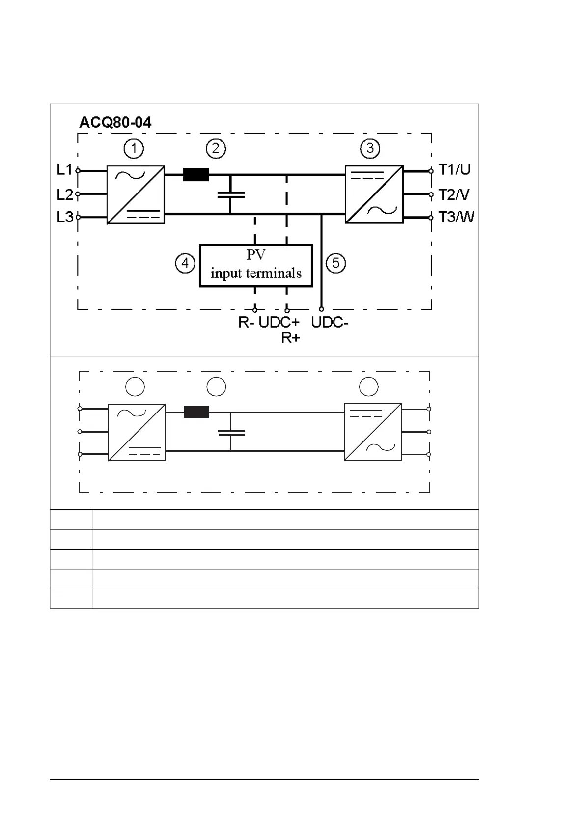
The figure below shows the simplified main circuit diagram of the drive.
Rectifier. Converts alternating current and voltage to direct current and voltage.1
DC link. DC circuit between rectifier and inverter.2
Inverter. Converts direct current and voltage to alternating current and voltage.3
UDC-, UDC+ in frames R0…R2 and R-, UDC+ in frame R34
DC connection (UDC+, UDC-) in frames R4…R8.5
Layout
■ Frames R0...R2
The layout of a frame R0 drive is presented below. The frame sizes R1…R2 is similar to
R0 but have a different structure.
26 Operation principle and hardware description

 Loading...


