44 Installation, Operation, and Maintenance
Part 1, Installation
2 Installation
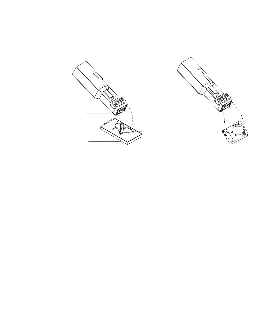
Front location Turn the injector so that the turret is facing the front of the GC.
Lower the injector until the alignment pin in the base enters the alignment
hole in the inlet cover. If using a G2916A tray, route the injector cable to the
right through the channel in the front of the tray and under the cable holder
(see Figure 8). If using a G2614A tray, route the cable to the right and under
the cable guide.
Back location Turn the injector so the turret faces the left side of the GC.
Lower the injector until the alignment pin in the base enters the alignment
hole in the inlet cover.
Figure 16 Mounting the injector
Hole
Alignment
Mounting
Alignment
6890 6850
post
pin
hole
Base
Note: 5890 Series II installation is not shown, but is similar to installation on a 6890.
 Loading...