64 Installation, Operation, and Maintenance
Part 1, Installation
2 Installation
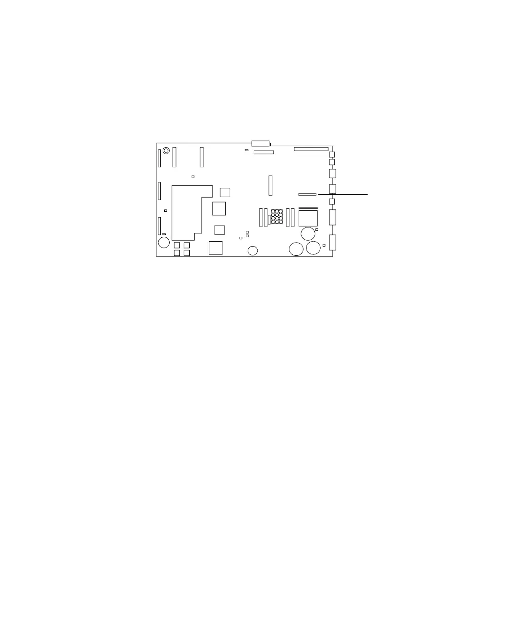
9 Connect the Controller PCB Cable, part no. G2612-60510, to the main board
at J8 and to the ALS Interface board at P5. Route the cable through the
cutout in the main board. See Figure 31 and Figure 33.
10 If an MIO card was removed from the GC, re-install it.
11 Using a nut driver, remove the cover plate over the 3 holes labeled
Injector 1 (default front), Injector 2 (default back), and Tray from the rear
panel. Save the plate and nuts so you can reinstall them to prevent access to
the high voltage area of the GC if you ever remove the ALS interface board
in the future.
12 Re-install the GC covers.
13 Restore power to the GC.
Figure 33 GC main board
J8, controller cable
connects here
 Loading...