112
ML-5120A
4. Setting the Laser Light Output Schedule
Making the Daily Check
The correction factor of soldering iron measured with a contact-type temperature is
recorded before shipping. We recommend that you carry out a periodic check as fol-
lows.
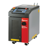
(1) Set the “LD” setting button to OFF and the “BEAM” and “GUIDE” setting buttons
to ON, and then adjust the position of guide light so that it falls on the following
position.
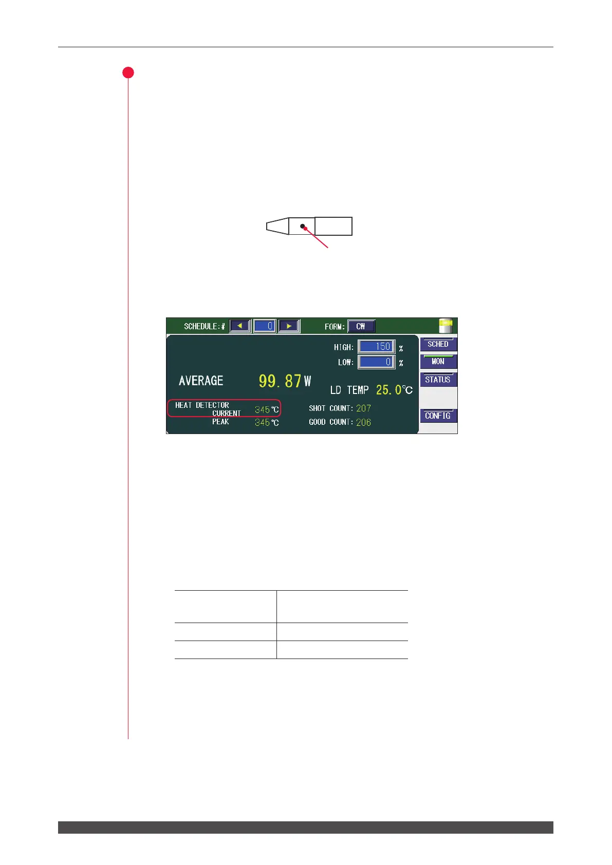
(2) After adjusting the position, set the “GUIDE” setting button to OFF and check the
temperature displayed on the MONITOR screen (HEAT DETECTOR CURRENT).
When the indicated temperature is low, check that the protective glass of the output
unit is not dirty. Note that the low temperature is also displayed in an environment
where there is much dust or gas, and humidity is high. On the contrary, when the
high temperature is displayed, check that there is no high-temperature heat source or
lighting nearby. If there are no problems in particular, adjust the correction factor to
use it.
⇒
The temperature detection area diers depending on the lens conguration. Re-
fer to the table below. The detection temperature is the average temperature.
Condensing lens
Temperature detection
area (focal position)
f70 Approx. φ1.2 mm
f120 Approx. φ1.6 mm
⇒
When the guide light is out of the focal position, the temperature detection area is
widened and the low temperature is detected.
⇒
The low temperature may be detected depending on the angle between the
workpiece and the output unit.
Guide light target position
Soldering tip
enlarged view
 Loading...