3. Connector Functions
141
ML-5120A
Chapter 4 Laser Processing by External Input/ Output Signals (EXTERNAL CONTROL)
Introduction Part Operating Part Maintenance Part Appendixes
Installation and
Preparation Part
REM. I/L Connector
The REM. I/L connector closes the safety shutter and connects the interlock to
cut o laser light in an emergency.
CAUTION
This connector can be used only when replacing our old products. Use the E-STOP
connector for the emergency stop signal in accordance with machine safety
standards.
⇒
Use the following attached connector.
Plug Case Manufacturer
116-12A10-2AF10.5 TAJIMI ELECTRONICS CO., LTD.
Pin No. Description
1
When the section between pin No.1 and pin No.2 is put an open circuit, the safety
shutter is closed.
2
⇒
When the section between 2 pins of this connector is opened by operating the
external interlock, the safety shutter is closed and both guide light and laser out-
put are stopped. Connect this connector to the main interlock, chamber interlock,
door interlock, or other interlock. A multiple number of these interlocks may be
connected in series as required. At delivery, the connector for short circuit is in-
stalled.
⇒
To release the interlock, put the section between pin No.1 and pin No.2 a closed
circuit and press the TROUBLE RESET button displayed on the laser controller.
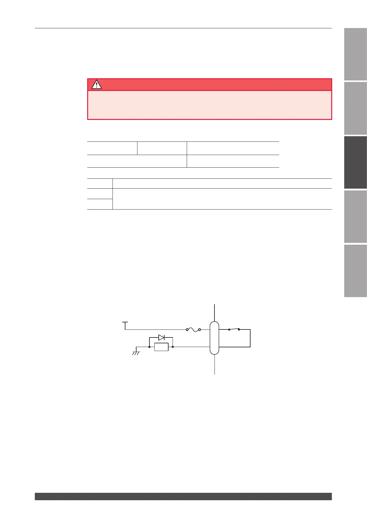
Inside of the laser
REM. I/L connector
+24V
External interlock
0V
RY
1
2
100 mA max.
 Loading...