User Manual – Rev BE AMETEK Programmable Power
MX Series 101
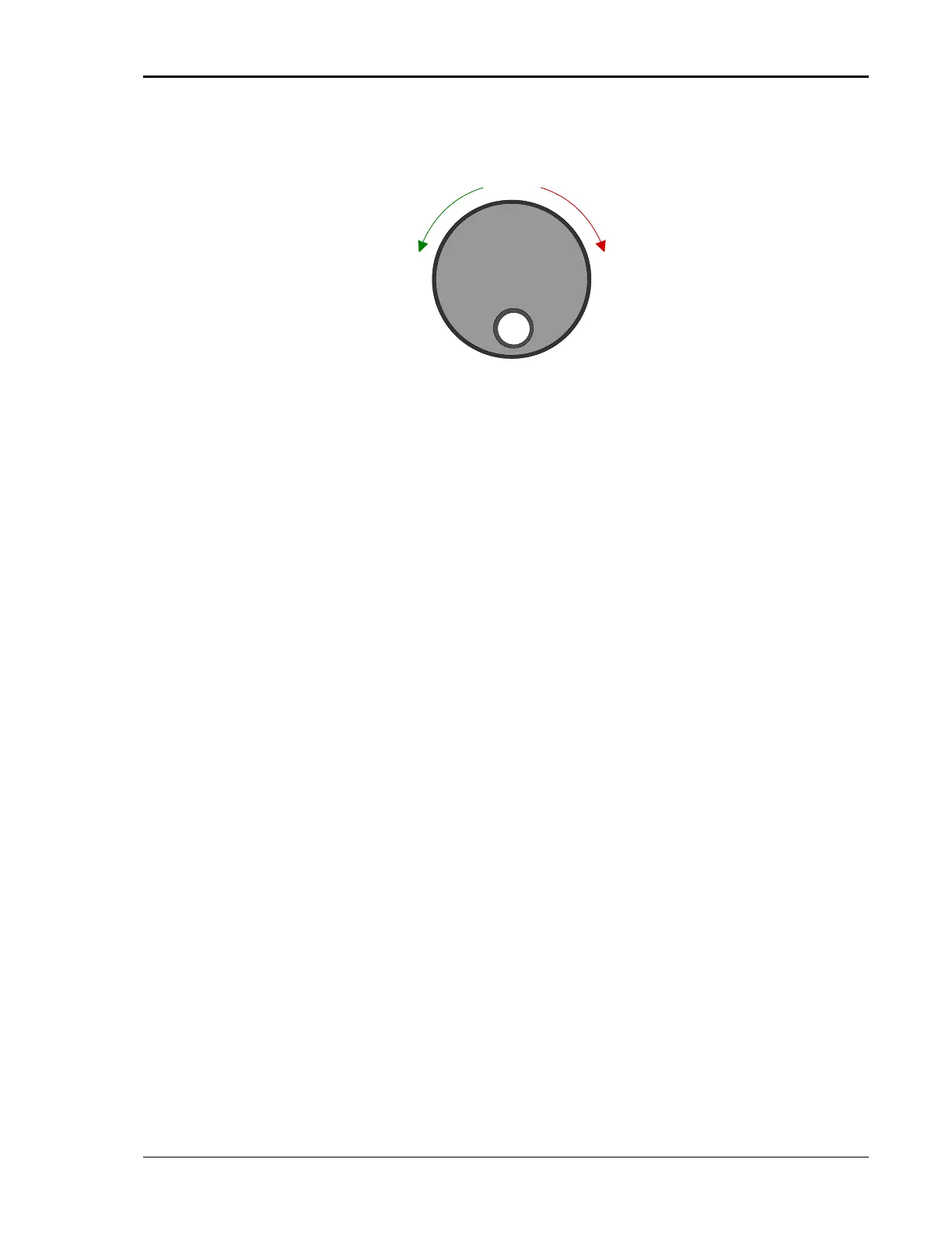
The Shuttle Knob
Figure 4-2: Shuttle Knob
The shuttle knob is located to the right of the LCD screen and is used to change
setup parameters. Note that it cannot be used to move the cursor position
between menu fields. Use the UP and DOWN arrow keys in the FUNCTION
keypad for this.
The shuttle knob can operate in one of two distinct modes of operation:
MODE DESCRIPTION
IMMEDIATE mode Any time the ENTER key is pressed, the MX Series
returns to its normal mode of operation. In this mode,
changes made with the shuttle knob, or the data entry
keypad will take immediate effect. The IMMEDIATE
mode is useful for slewing output values such as
voltage and frequency and observing the effect on the
load.
SET mode When the SET key located in the FUNCTION keypad is
pressed, changes made with the shuttle to any output
parameter will not take effect until the ENTER key is
pressed. In this mode, any changes made to a setup
menu will be blinking to indicate the pending change
condition. This mode allows changes to be made to all
output parameters and executing them all at once by
pressing the ENTER key.
Clockwise
INCREM ENT
DECREM ENT
Counter Clockwise