User Manual – Rev BE AMETEK Programmable Power
MX Series 260
POWER INTERRUPT
This test requires a numeric entry value equal to the test number. The tests are
grouped as follows:
• Test numbers 1 through 15 are for all Standard and Groups. See Figure 9-6 for
details of the tests.
• Test numbers 16 and 17 for all equipment that does not incorporate digital circuit.
Test number 16 will drop the output to zero voltage for 50 ms. Test number 17 will
drop the output to zero voltage for 200 ms. Test number 18 is used for DC equipment
and will drop the output for 1 sec.
• Test numbers 21 through 26 are applicable for Groups 2 and 3 only. Output frequency
will be set to the F1 value for 1 second prior to the test. The output frequency will
remain set to the F2 value when the test is completed. This will allow the user to apply
sequence of power interrupts. See Figure 9-7 for detail of the tests.
DO160 Table 9-6: Test conditions for equipment with digital circuits.
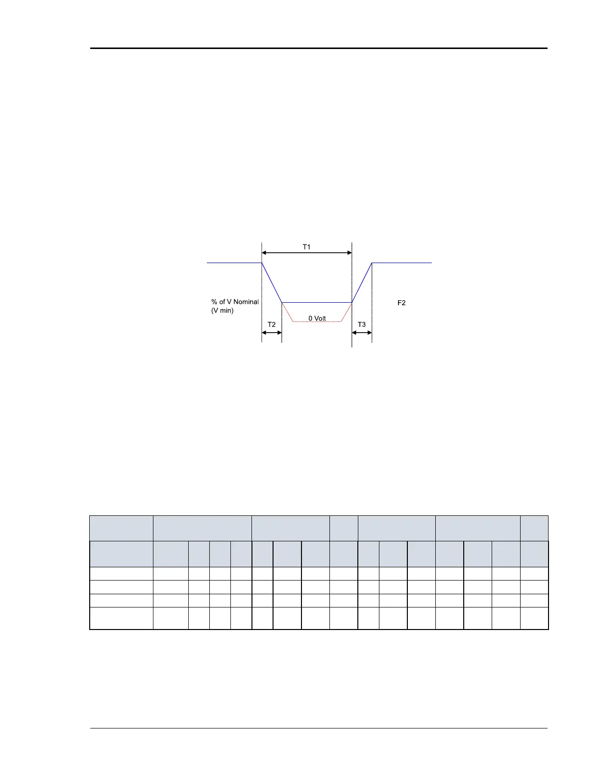
• Definitions:
• T1 Power interrupt time
• T2 Time it would take for the applied voltage to decay from V (nom) to zero volts.
• T3 Time it would take for the applied voltage to rise from zero to V (nom) volts.
• V MI N The minimum level (expressed as a percentage of V NOMINAL) to which the applied voltage is permitted to decay.
• Tolerance T1, T2, T3 = ± 10%
Test condition numbers 8 and 15 are for category Z, dc powered equipment
only.
Applicable
Ca t e g or y:
T1 ( ms ) 2 ** 10 25 50 75 100 200 1000 10 25 50 75 100 200 1000
T2 ( ms ) <1 20* 20 20 20 20 20 20 50* 50* 50 50 50 50 50
T3 ( ms ) <1 5 5 5 5 5 5 5 20 20 20 20 20 20 20
%V No m .
(V min)
0 50 15 10 5 0 0 0 80 50 0 15 5 0 0
* Voltage will not reach zero in this test condition.
** Equipment performance standards may require repeating test n°1 with T1 varying from 5 to 200 ms by step defined in the test equipment
performance standards (step typically comprised between 5 ms and 20 ms depending on equipment design.
Figure 9-6: Power Interrupt