User Manual – Rev BE AMETEK Programmable Power
MX Series 270
For Star (Wye) connected three-phase EUT’s,.voltage dips should be performed
on both individual Line-to-Neutral voltages as well as on all three Line-to-Line
voltages. Thus, each test should be run 6 times, each time selecting a different
phase option: A, B, C, A+B, A+C and B+C.
For Delta connected three-phase EUT’s,.voltage dips, only Line-to-Line voltages
dips have to be run. Thus, each test can be run 3 times, each time selecting a
different phase A+B, A+C and B+C.
Note that the –411 option in MX Series AC sources with Firmware revision lower
than 1.13 will not support 2 phase out of 3 selections. MX Series I systems with
firmware revision 1.17 or higher and MX Series II systems with firmware
revision 4.17 or higher support three phase dips testing using the preferred
method referenced in figure 4b) (A) of IEC 61000-4-11, Edition 2.0. MX units
with revisions prior to this will change the L-N amplitude by the set dip level but
retain the normally programmed phase angle relationship. For firmware
upgrades, contact techsupport.ppd@ametek.com
.
Note that required phase angles and amplitudes are automatically set for dips of
0, 40, 70, 80 and 100% to conform with method (A). For all other dip levels,
method (A) can be used by programming the required phase angles to be used
during the programmed dips. The amplitude and phase angles required to
obtain the correct line-to-line voltage dip per method (A) for standard dip levels
of 40, 70 and 80% are embedded in the firmware and conform to table C.2 of
IEC 61000-4-34.
Since all phase programming on the MX series is referenced to phase A, voltage
dip with a phase angle for A other than 0° are implemented by offsetting all
three phases by the required number of degrees to get phase A at 0°. This is
reflected in the actual output settings shown on the MX versus the data in table
C.2 of the IEC61000-4-34. The actual output settings are shown in the last 3
columns.
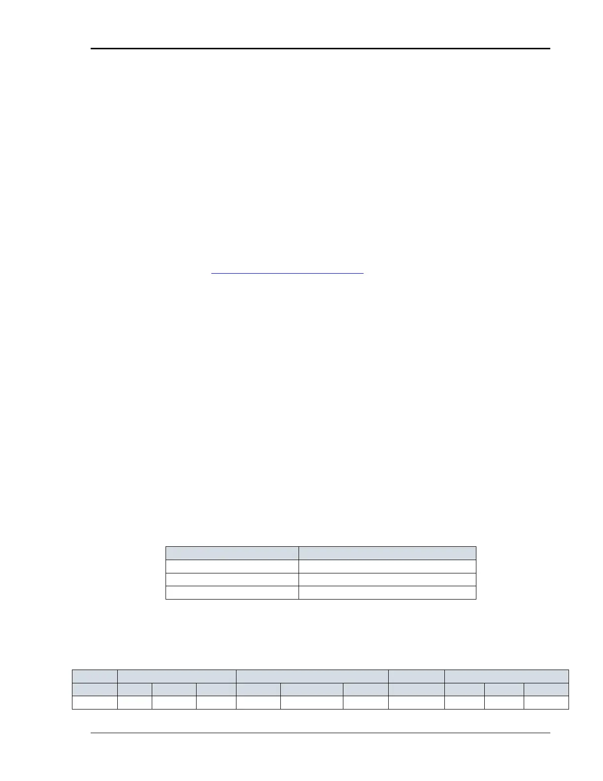
Phase Mapping
The phase rotation on the MX series is ACB. This means phase A is mapped to
L1, phase B is mapped to L3 and phase C is mapped to L2. The required phase
selection letter combination for the required Line-to-line dip is shown in table
C.2 for reference.
L1 A
L2 C
L3 B
Table 9-17: Phase Mapping
To select the desired phase-to-phase dip, select the phase selection as shown in
column 8 and either 80, 70 or 40 % dip level from the IEC411 screen or the
Gui. Table C.2
100% dip 100 % 100 % 100 % 100 % 100 % 100 % n/ a 100 % 100 % 100 %
 Loading...


