User Manual – Rev BE AMETEK Programmable Power
MX Series 59
3.6.2 Output Terminal Blocks
The MX30-3, MX30-3Pi, MX45-3 and MX45-3Pi have two output terminal blocks,
TB1A and TB1B. The MX45-1 only has one output terminal block, TB1B. The
terminal blocks are large enough to accommodate the recommended wire gauge
sizes shown in Table 3-2. The terminal blocks are in the lower right corner on
the front of the unit. The front panel needs to be removed to access these
terminal blocks.
CAUTION: REMOVE ALL INPUT POWER TO THE MX BEFORE REMOVING
THE FRONT PANEL.
The correct standard size Allen wrenches for connecting output wiring to TB1A
and/or TB1B are supplied with each MX in the ship kit. Look for a brown
envelope. If the correct tools cannot be found, contact AMETEK Programmable
Power customer service at repair.ppd@ametek.com
.
Terminal block TB1B always provides the output neutral connection, regardless
of the phase mode (1 or 3 phase output mode).
In single-phase mode, phase A output is provided through terminal 1 of TB1B.
In three-phase mode, phase A, B and C outputs are provided through terminals
1, 2 and 3 of TB1A, respectively.
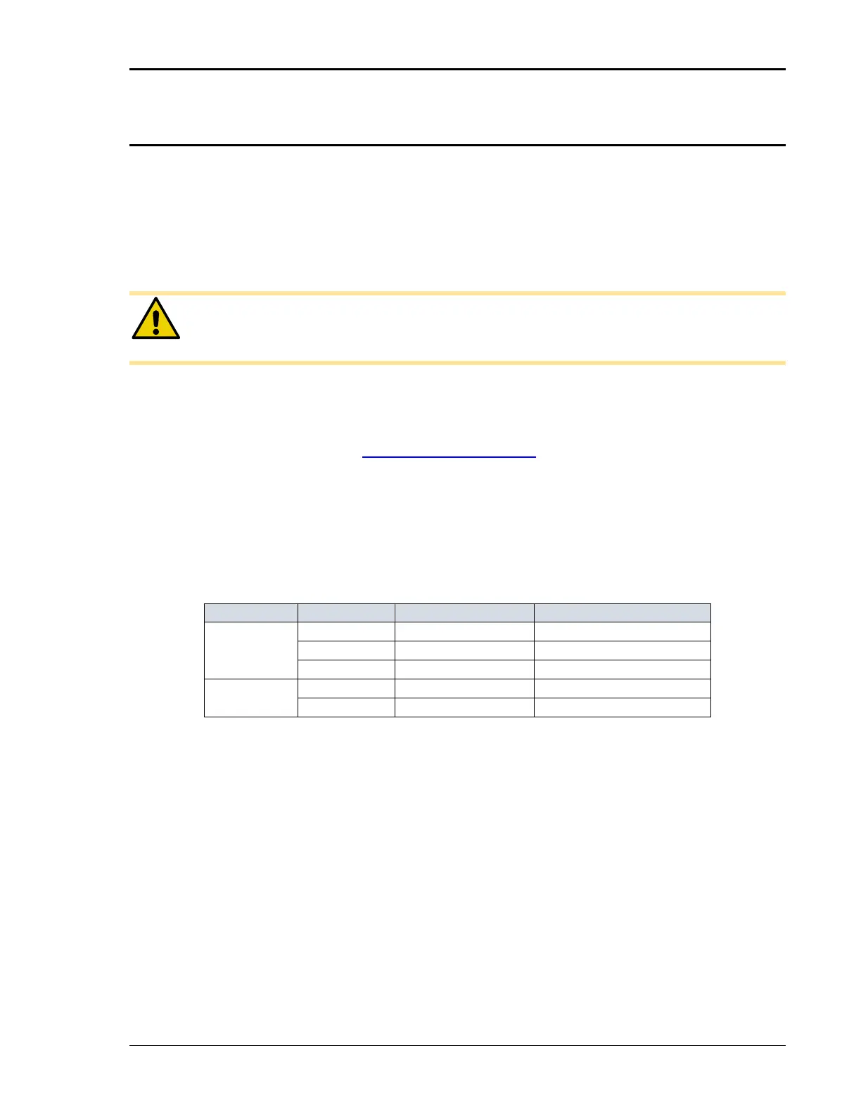
TB1 A
1 3 Phase Phase A
2 3 Phase Phase B
3 3 Phase Phase C
TB1 B
1 1 Phase Phase A
2 1 and 3 Phase Neutral
Table 3-3: Output Terminal Connections.