User Manual – Rev BE AMETEK Programmable Power
MX Series 230
Current Limit Calibration
NOTE: This procedure only applies to MX Systems with top assembly
P/N 7003-400-1 (Series I). If the MX system is P/N 7003-422,
this section can be skipped. To check the model top assembly
part number, consult the model and serial tag on the rear on
the MX chassis.
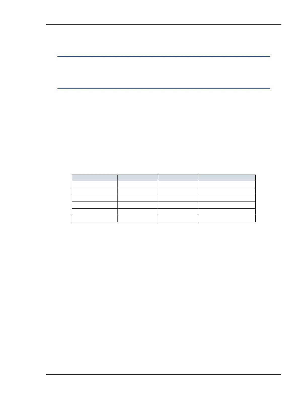
Program the output to 135V, 60Hz on the low range. Program the current limit
to IPROG in Table 6-5 below, set limiting mode to Constant Current (CC).
Apply 105 to 110% of IPROG load to phase A output. Now adjust R195 on the
system interface board (P/N 7003-700-1) until the output current is 103% of
IPROG (ISET).
When this adjustment is being made the front panel OVERLOAD indicator should
be lit.
If system is 3-phase, then proceed to the phase B output and adjust R196 as
above. For phase C output adjust R197.
MX3 0 -1 200 206 R195
MX3 0 -1 66 68 R195, R196, R197
MX4 5 -1 300 309 R195
MX4 5 -3 100 103 R195, R196, R197
MX9 0 200 206 R195, R196, R197
MX135 300 309 R195, R196, R197
Table 6-5: Current Limit Calibration
Repeat this adjustment for the Phase B and Phase C if present.