User Manual – Rev BE AMETEK Programmable Power
MX Series 274
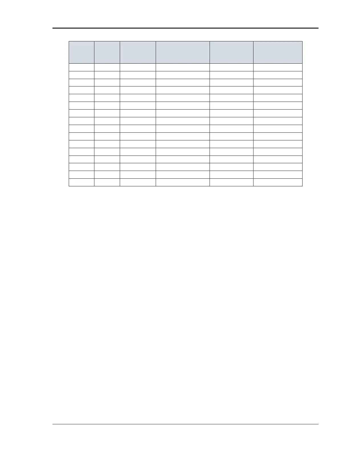
Delay between
repeats (s)
6 0 25 180,225,270 3 at diff ø 10
7 0 50 270,315,0 3 at diff ø 10
8 40 0.5 0 3 10
9 40 0.5 180 3 10
10 40 1 0,45,90 3 at diff ø 10
11 40 5 45,90,135 3 at diff ø 10
12 40 10 90,135,180 3 at diff ø 10
13 40 25 180,225,270 3 at diff ø 10
14 40 50 270,315,0 3 at diff ø 10
15 70 0.5 0 3 10
16 70 0.5 180 3 10
17 70 1 0,45,90 3 at diff ø 10
18 70 5 45,90,135 3 at diff ø 10
19 70 10 90,135,180 3 at diff ø 10
20 70 25 180,225,270 3 at diff ø 10
21 70 50 270,315,0 3 at diff ø 10
Table 9-19: Dips and Interruptions Tests Performed During RUN ALL
The user can change the NOMINAL Ut voltage for this. The RUN ALL Command
line will change to ABORT during the test. Selecting ABORT and pressing the
ENTER key will terminate the test at any time and the output voltage will return
to the nominal value.
PHASE SELECTION
Voltage Dips and Interruptions can be run on an individual phase, two phases or
all three phases. The PHASE key on the front panel can be used to select the
desired phase mode. The active phase mode is indicated in the upper right-hand
corner of the LCD display.
On MX Series with firmware revision 1.13 or higher, it is also possible to select
two out of three phases. This allows line-to-line voltage drops as called out in
Edition 2.0 of the IEC 61000-4-11 to be performed as well.
RUN SINGLE
RUN SINGLE command will run a single test once. The Dip or Interrupt test is
defined by the DIP TO, NO CYCLES, and START ANGLE parameters. These
parameters must be set before starting the test. The following is a description
of these parameters.
DIP TO:
The dip voltage level as a percentage of the nominal voltage.
NO CYCLES: