User Manual – Rev BE AMETEK Programmable Power
MX Series 75
32
DC: DC mode control
33
I NP OFF: Input power control
34
A ERR HI : Error Signal Phase A, high
35
N/ C
36
B ERR LO: Error Signal Phase B, low
37
C ERR HI : Error Signal Phase C, high
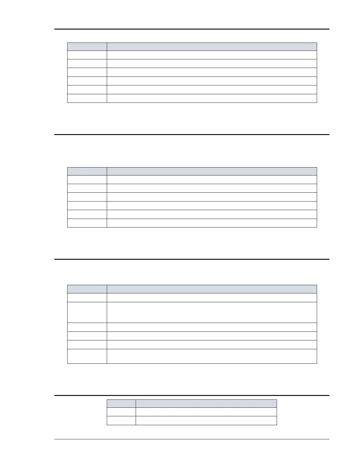
Table 3-4: System Interface Connectors
3.7.2 Analog Input Connector
Input screw-terminal strip. Functions are called out on rear panel decal. Table
shows connections from left to right when standing at the rear of the MX
cabinet.
1
RP V HI . INPUT: Analog input for External Modulation
2
RP V Lo . INPUT: return.
3
E XT S YN C H I INPUT: Analog input for external sync mode.
4
E XT S YN C Lo INPUT: return.
5
RI : INPUT: Remote Inhibit. (See paragraph 3.12.)
6
RI : INPUT: return.
Table 3-5: Analog Interface Connector
3.7.3 BNC Connectors
BNC connectors. Functions are called out on rear panel decal. Table shows
connections from left to right when standing at the rear of the MX cabinet.
1
Trigger Input (TTL input)
2
Tr i g g e r Ou t p u t ( TTL output) (Same signal connection as Function Strobe. Some units may not have this output
connected. If you do not get an output trigger on this BNC connector, use the Function Strobe BNC connector
instead.)
3
Function Strobe (TTL output) (Same signal connection as Trigger Output)
4
Clock (TTL output on Master / TTL input on Auxiliary)
5
Lock (TTL output on Master / TTL input on Auxiliary)
6
Emergency Shut off interconnect. Installed only on –MB systems with –ES Op t i on (no longer required for MX units
with the –ES Option shipped January 2017 and later).
Table 3-6: BNC Connectors
3.7.4 External Sense Connector
1
Phase A sense
2
Phase B sense