User Manual – Rev BE AMETEK Programmable Power
MX Series 94
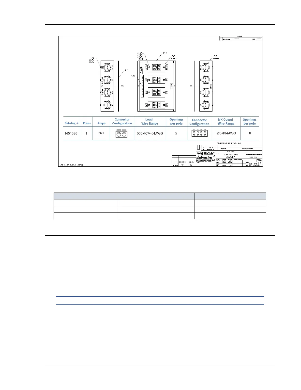
Figure 3-22: 7003-416-1 Output Junction Box
DIMENSIONS 7003-416-1 OUTPUT JUNCTION BOX:
Chassis Dimension W x L x H 12.125 “ x 16.125” x 4.125” 308 x 410 x 105 mm
Feet height: 0.875 22 mm
Strain relief hole size: 1.5” diameter 38 mm diameter
3.14 Output Filter Box Accessory
An optional output filter box (P/N 7003-424-1) is available which may be used
reduce the amount of ripple and noise present at the output of the MX30/45-
3Pi.
The filter must be connected between the three-phase output of the MX30/45
and the unit under test. To access the connection terminal blocks, the top cover
of the filter case must be removed.
NOTE: Make sure all power is off when connecting the filter accessory.
The output of the MX30/45 is connected to the input side of the filter. Use
terminal blocks TB1A (phases A and B) and TB1B (phase C and neutral) as
indicated in Figure 3-23. The load can be connected to the load side of the filter
box using terminal blocks TB2A and TB2B. Do not swap phases through the
filter.