User Manual – Rev BE AMETEK Programmable Power
MX Series 165
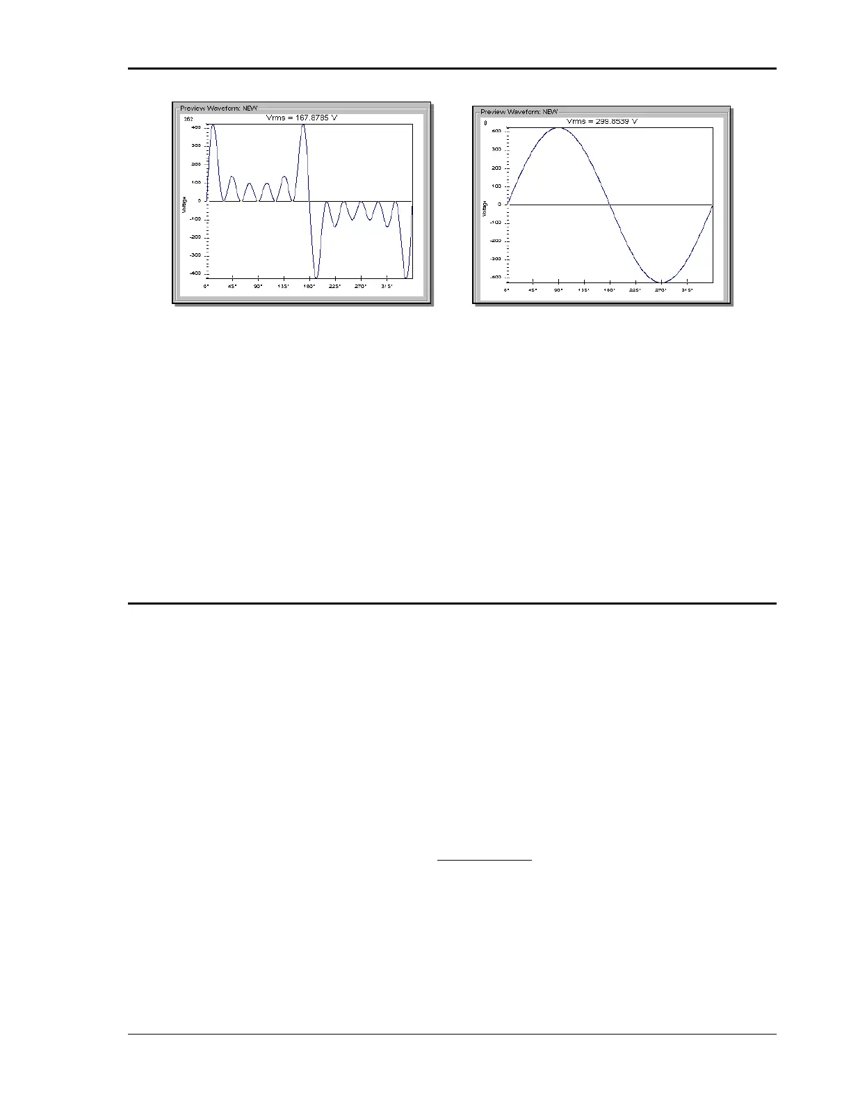
Figure 4-35: Waveform Crest Factor Affects Max. RMS Voltage
The figure shown here illustrates the relationship between the crest factor of the
wave shape (or its “peakiness”) and the maximum peak voltage allowed for a
given voltage range. Since the peak voltage cannot exceed the AC source’s
capabilities, the programmable RMS voltage must be restricted, in this case to
only 167.8785 volt for the waveform on the left. The sine wave on the right can
be programmed to the full 300 V rms as this still falls within the same peak
voltage limitation of the AC source.
If the MX Series is used over the bus, the “:VOLT? MAX” query command can be
used to determine the maximum allowable RMS voltage for the selected
waveform. Using the returned value as part of a program will prevent range
errors.
4.4.6 Frequency Response Restrictions
The user may create a waveform that contains any number of harmonic
frequencies of the fundamental. The AC Source itself however has a finite signal
bandwidth and will attenuate higher frequency components of the signal. To
limit the maximum frequency component of the output signal, the 3Pi controller
automatically applies a band-pass filter to all custom waveforms as they are
downloaded. The controller implements the following process for user defined
waveforms:
Each down loaded waveform will have a computed frequency limit that is less
than or equal the maximum frequency limit of the AC source. The frequency
limit is a function of the harmonics content of the waveform and will follow the
equation below.
ℎ
=
( × ℎ)
If F
maxh
is below the minimum frequency limit, the waveform will be rejected at
download time and the label will be deleted from the waveform catalogue.
If the MX Series is used over the bus, the “:FREQ? MAX” query command can be
used to determine the maximum allowable fundamental frequency for the