User Manual – Rev BE AMETEK Programmable Power
MX Series 79
3.7.6 USB Interface
A standard USB Series B device connector is located on the rear panel for
remote-control. A standard USB cable between the AC Source and a PC or USB
Hub may be used.
NOTE: Use of the USB port to control more than one power source from
a single PC is not recommended, as communication may not be
reliable. Use GPIB interface for multiple power source control.
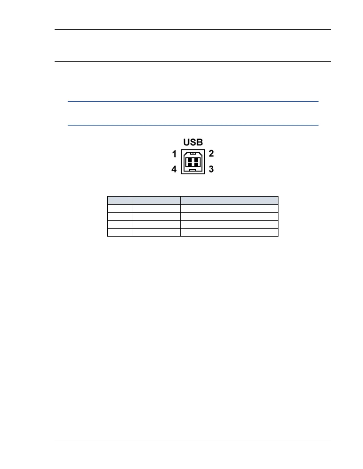
Figure 3-16: USB Connector Pin Orientation.
1 VBUS + 5 VDC
2 D- Data -
3 D+ Data +
4 GND Gr o u n d
Table 3-10: USB Connector Pin-out.