User Manual – Rev BE AMETEK Programmable Power
MX Series 77
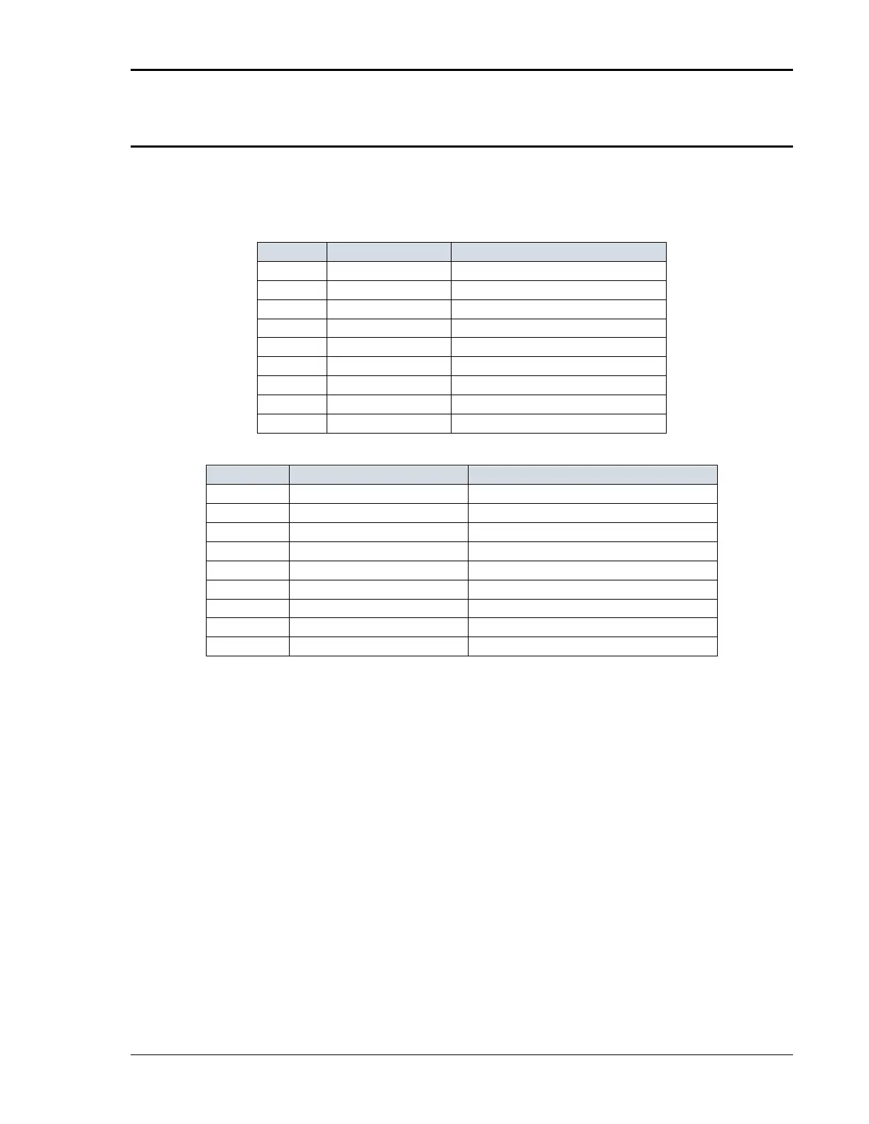
3.7.5 RS232C Serial Interface Connector
An RS232 serial interface connector is located on the rear panel on all models.
Note that two versions of the RS232 exist on the MX model series depending on
the age of the unit. Older models can be identified by the fact that they will not
have a USB interface.
1 N/ C
2 TxD Output
3 RxD Input
4 N/ C
5 Common Common
6 N/ C
7 CTS Input
8 RTS Output
9 N/ C
Table 3-8: RS232 Connector Pin-out – MX with RS232 and USB.
1 N/ C
2 RxD, Re ce ive d a t a Output
3 TxD. Tr a n s mi t d a t a Input
4 DTR, Data Terminal Ready DTR, Data Terminal Ready
5 Common Common
6 N/ C N/ C
7 RTS, Request to Send Output
8 N/ C N/ C
9 N/ C N/ C
Table 3-9: RS232C Connector Pin-out – MX with RS232 but no USB
On MX models without a USB interface, a special RS232 cable is required to
connect to a PC. With these MX models, a special 13 foot (4 meters) cable is
supplied in the MX Series ship-kit. The wiring diagram for this cable is shown
below in case a longer cable needs to be constructed. Alternatively, a generic
straight thru DB9 male to DB9 female cable can be used to extend the supplied
cable.
MX models that have both RS232 and USB interface use a more common
straight through DB9 male to DB9 female serial cable, which is supplied in the
MX ship kit for these models.