User Manual – Rev BE AMETEK Programmable Power
MX Series 82
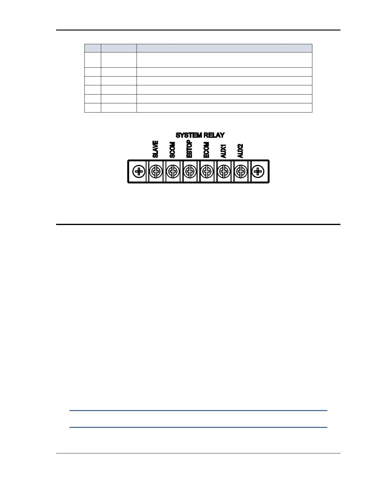
1 S LAVE
24V DC Master Select. Connection is made to Master Chassis only. 24VDC /10mA to set a
Master unit into AUX mode.
2 SCOM
SLAVE Common.
3 ESTOP
24V DC Enables Output. 0V DC Disables Output
4 ECOM
ES TOP Co m m o n .
5 AUX1
Reserved
6 AUX2
Reserved
Table 3-12: Master Select and Emergency Stop Switch
Figure 3-19: SLAVE and ESTOP interconnect at the rear panel
3.8 Multiple Cabinet System Configurations (incl. –MB)
Multi-cabinet MX models consist of two or three autonomous or Auxiliary MX45-
3Pi units. Auxiliary units do not have their own controller and are identified
easily by their blank front panel (except for status indicator LEDs). Master units
each have their own controller but can be configured as auxiliary units by
disconnecting the ribbon cable marked J17 between the controller and the
system interface board (P/N 7003-700-1 or P/N 7003-715-1). This disables the
controller and allows the MX45 to operate as an Auxiliary unit. (Requires
removal of the top cover). See section 4.2.11.5 for information on setting the
SYSTEM field in the configuration menu when changing configurations on MX
systems with the –MB (Multi-box) option.
When used as a multi-cabinet system for higher power applications, the
controllers in the unit(s) acting as the auxiliary to the master are either disabled
or not present. For normal system configurations such as MX90-3Pi, the
auxiliary unit will not have a controller or front panel and will have been factory
configured for auxiliary operation.
For –MB systems such as MX90-3Pi-MB, the controller in the auxiliary unit must
be disabled using S1. The SYSTEM field in the master unit controllers
CONFIGURATION SETUP 3 screen must be set to the correct system
configuration setting as well. The SYSTEM field for the controller in the auxiliary
unit must be set to AUX if it is used as an auxiliary unit. See section 4.2.11.5.
NOTE: New SYSTEM field configuration settings do not take effect until
power is cycled.